FAQ
TL;DR: 15 answers, “remote_io:26” is the clue: this FAQ helps MHCOZY TYWRA-RF owners configure a CB3S BK7231N dry-contact relay after OpenBeken flashing, restore WiFi access, wire UART safely, and understand why 433 MHz RF learning may stay outside MCU control. [#21782497]
Why it matters: A correct pin map and safe flashing method can preserve relay control, avoid regulator damage, and clarify whether RF pairing belongs to OpenBeken or the separate RF circuit.
| Option |
Hardware path |
What the thread shows |
Practical result |
| OpenBeken on BK7231N |
CB3S WiFi MCU |
Relay on P24, WiFi LED on P8, buttons on P6/P14 |
Local WiFi relay control |
| Original Tuya RF behavior |
RF receiver/decoder section |
Tuya dump includes remote_add_dp 49, remote_list_dp 50, remote_io 26 |
RF learning may depend on RF chip support |
| Separate RF chip path |
RFE2740/RFE2740DM plus radio chip |
RF chip can simulate button GPIOs |
RF can work independently of CB3S firmware |
| Zigbee replacement |
Different module ecosystem |
One user chose Zigbee after hardware damage |
Simpler replacement path after failed repair |
Key insight: The MHCOZY TYWRA-RF is not just a BK7231N relay. Its 433 MHz learning path may involve an RFE2740-class RF chip, so OpenBeken pin mapping alone does not guarantee RF pairing.
Quick Facts
- The shared OpenBeken template identifies the device as Tuya MHCOZY TYWRA-RF, chip BK7231N, board CB3S, with dry contact, 5V, USB, and RF 433MHz keywords. [#20606758]
- Core OpenBeken pins from the first working config are P6
Btn;0, P8 LED_n;0, P14 Btn;0, and P24 Rel;0. [#20606758]
- Tuya extraction lists LED channel 1 on P9, Pair/Toggle All Button on P6, WiFi LED on P8, channel toggle on P14, and relay on P24. [#21308431]
- Flashing access used CB3S UART points: PIN1 CEN, PIN8 Vcc, PIN9 GND, PIN15 RX, and PIN16 TX. [#21324150]
- RF-related Tuya fields include
remote_add_dp:49, remote_list_dp:50, remote_io:26, rf_width:345, and remote_select:1 in one later dump. [#21324150]
How do I configure an MHCOZY TYWRA-RF dry contact relay module with a CB3S BK7231N chip after flashing OpenBK7231T/OpenBeken?
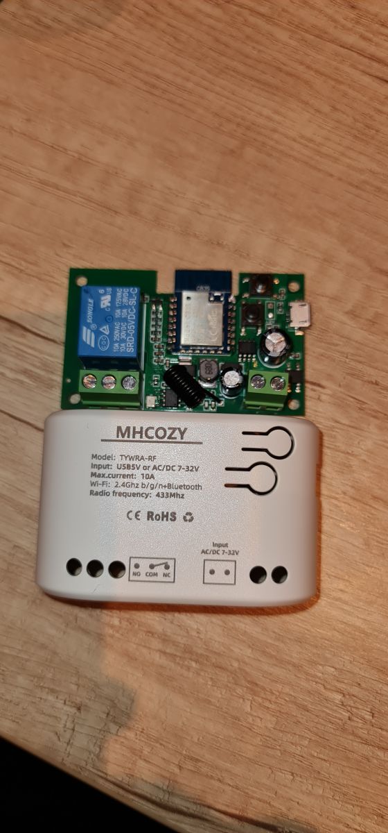
Configure it as a Tuya MHCOZY Relay module, model TYWRA-RF, chip BK7231N, board CB3S. Use the shared OpenBeken-style map: P6 button, P8 inverted LED, P14 button, and P24 relay. The original JSON names the device “MHCOZY Relay module (dry contact)” and lists 5V, USB, and RF 433MHz as keywords. This gives WiFi relay control after flashing, but does not prove RF learning works.
[#20606758]
What pin configuration should I use for the MHCOZY TYWRA-RF relay module with CB3S, including relay, buttons, and LEDs?
Use P24 for the relay, P8 for the WiFi LED, P6 for the pair or toggle-all button, and P14 for channel toggle. A Tuya extraction also found channel LED on P9. The first shared OpenBeken config used
Btn;0 on pins 6 and 14,
LED_n;0 on pin 8, and
Rel;0 on pin 24. That matches the later Tuya pin summary.
[#21308431]
How can I teach or learn a new 433 MHz RF remote on an MHCOZY TYWRA-RF relay after flashing the BK7231N firmware?
Use RF support only if your build and wiring expose the RF receiver to OpenBeken. The later thread points to an RF receiver driver guide and highlights
remote_io:"26" from the Tuya extraction. That field is the only concrete RF GPIO clue in this thread. If your board handles RF inside a separate decoder chip, OpenBeken cannot learn the remote through normal relay pins alone.
[#21782497]
Why does the MHCOZY TYWRA-RF relay become only WiFi-controlled after flashing, and what happens to the RF remote function?
It becomes WiFi-controlled because flashing replaces Tuya firmware on the CB3S BK7231N module. A user asked why it was “just a wifi controlled relais” after flashing. RF learning may disappear when Tuya datapoints and RF routines are no longer active. In one 4-channel related board, RF decoding appeared separate from CB3S and only simulated button presses.
[#20801332]
What is the correct UART wiring for flashing a CB3S module on an MHCOZY TYWRA-RF relay?
Wire the CB3S UART as PIN1 CEN, PIN8 Vcc, PIN9 GND, PIN15 RX, and PIN16 TX. One user described this as the standard CB3S connection. If powering through the relay’s micro USB port, connect only RX, TX, and GND from the adapter. Then reset or power-cycle when the flasher requests boot mode. Keep UART at 3V logic.
[#21324150]
How do I flash a BK7231N CB3S relay module using the Windows BK7231 UART flasher?
Flash it through UART, then reset the CB3S into boot mode when prompted. One successful Windows sequence was:
- Wire TX, RX, and GND.
- Start the Windows BK7231 UART flasher, then power the switch by USB.
- Briefly connect GND to PIN1 RST, then disconnect GND.
This user warned that incorrect TX/RX handling coincided with SMD damage. [#21325559]
What should I do when a flashed BK7231N relay gets an IP address from the router but the web interface will not open?
Use UART configuration first, because the relay can accept parameters without the web interface. One user reported the router assigned an address, but the browser could not reach the relay. The same user could still change parameters through UART. That makes UART the practical recovery path before reflashing or replacing hardware.
[#21311074]
How can I set WiFi SSID and password through UART when the OpenBeken access point does not appear?
Set WiFi credentials by editing the OBK config over UART. The reported sequence is: choose “Read only OBK config,” then “Change OBK settings,” enter SSID and password, and finally “Write only OBK config.” No WiFi flag boxes are needed for this step. This applies when the OpenBeken AP does not appear after flashing.
[#21325677]
What does the Tuya extracted configuration mean for pins like rl1_pin, netled1_pin, total_bt_pin, remote_io, and remote_select?
Those fields map Tuya functions to physical pins and RF behavior.
rl1_pin:24 means relay 1 uses P24.
netled1_pin:8 means the WiFi LED uses P8.
total_bt_pin:6 means the pair or toggle-all button uses P6.
remote_io:26 marks an RF-related input, while
remote_select:1 enables the remote path in that dump.
[#21324150]
What is a dry contact relay, and how is it different from a normal powered relay output?
A dry contact relay switches an isolated contact rather than supplying its own output voltage.
"Dry contact relay" is a relay output category that opens or closes an electrically isolated contact, letting an external circuit provide the voltage, unlike a powered output that drives load voltage directly. The thread names this device “MHCOZY Relay module (dry contact)” and lists 5V USB power.
[#20606758]
What is a CB3S module, and how is it related to the BK7231N chip used in Tuya devices?
CB3S is the WiFi module that carries the BK7231N chip in this relay.
"CB3S module" is a Tuya-style WiFi module that contains the BK7231N MCU, exposes pins such as CEN, RX, TX, Vcc, and GND, and runs the firmware replaced by OpenBeken. The Tuya extraction explicitly says module CB3S and BK7231N.
[#21308431]
What is an RFE2740 or RFE2740DM RF chip, and how might it handle 433 MHz remote learning independently of the CB3S MCU?
RFE2740DM can act as a separate RF decoder that learns remotes and triggers button GPIOs.
"RFE2740DM RF chip" is an RF remote-control decoder IC that connects to a radio receiver and button lines, learning RF codes and simulating button presses without needing CB3S firmware logic. A related 4-channel board used RFE2740DM, WL520, one RF wire, and 4 button wires.
[#21795126]
BK7231N vs ESPHome vs Zigbee relay modules — which is better for replacing Tuya firmware in smart relay projects?
Choose BK7231N/OpenBeken when you want to reuse this CB3S WiFi relay. Choose ESPHome only if your target firmware supports the exact hardware path you need. Choose Zigbee when you prefer replacing the module instead of repairing or debugging UART damage. One user stopped after an AMS1117 repair failed and bought a Zigbee switch.
[#21327020]
How do I make an OpenBeken relay turn off automatically 1 second after pressing a button?
Set an auto-off action in OpenBeken so the relay turns off 1 second after the button event. The thread only asks this requirement and gives no confirmed command. The concrete target is clear: after pressing the button, the relay must turn off after 1 second. Use the device’s relay channel on P24 when creating the automation.
[#21624939]
What safety checks should I do before powering a CB3S relay board by USB while connecting RX, TX, GND, CEN, or RST for flashing?
Check power polarity, logic voltage, ground reference, and reset wiring before applying USB power. Use 3V UART logic, connect GND between adapter and board, and avoid feeding a weak 3V3 rail through the adapter. One safer method used USB for relay power and only RX, TX, and GND for UART. A smoking AMS1117 indicates a serious power fault.
[#21324638]
AI summary based on the discussion. May contain errors.






Comments
Yes thnx this wil help, but now it is just a wifi controlled relais, how can i learn a new RF remote control? [Read more]
Hi, did anyone solve this problem? Thanx [Read more]
are you sure RF matching must be done through software? I notice the manual only makes mention of the app method, but my experience with the switches I have with RF capability is that a long-push of one... [Read more]
Hi, I have the instructions manual. But xinetic mentioned that the RF transmitter cannot be learned after flash, so far I relay not flash because I want to keep the RF function. I will try to pick up... [Read more]
I flashed the relay successfully, it connects to wifi but cannot connect to the web interface :-( It's there way to reach settings in another way? [Read more]
Hi, does anyone have experience with this problem. The relay has an address assigned to it by the router, but i cannot connect to it after entering the address into the browser. I can change the parameters... [Read more]
Hi, I have the same smart switch. Can you tell me how you flashed it? Did you connect an uart/usb device, and if so, how did you wire it? [Read more]
Hi, standard conection via UART, module CB3S: PIN1 - CEN PIN8 - Vcc PIN9 - GND PIN15 - RX PIN16 - TX { "rl1_lv":"1", "on_off_cnt":"10", "onoff_rst_m":"0", "led1_pin":"9", "onoff_clear_t":"6", "rand_dpid":"42", "net_trig":"4", "netled1_lv":"0", "jv":"100", "onoff_rst_type":"2", "total_bt_pin":"6", "nety_led":"0", "total_stat":"0", "reset_t":"5", "netled1_pin":"8", "remote_add_dp":"49", "remote_list_dp":"50", "net_type":"0", "inch_dp":"44", "rf_width":"345", "module":"CB3S", "ch_cddpid1":"9", "remote_io":"26", "onoff1":"14", "init_conf":"38", "led1_lv":"0", "zero_select":"0", "onoff_type":"0", "series_ctrl":"0", "total_bt_lv":"0", "cyc_dpid":"43", "remote_select":"1", "ch_num":"1", "rl1_pin":"24", "netn_led":"0", "ch_dpid1":"1", "crc":"16" } Device... [Read more]
That's how I connected it, but I did not unsoldier the cb3s. I tried to reset through pin 1 (reset) and pin 3 (cen), but without luck. Do I have to unsoldier the cb3s for that? I measured voltage over... [Read more]
That's weird. If you have a weak 3V3 power supply on the UART, you can use an external stabilizer. But the easiest way is to just connect Rx, Tx and GND and power the relay through its micro USB port.... [Read more]
Your suggestion did help me, but it works differently for me. Steps I did: 1. wire TX, RX and GND 2. connect USB/UART to computer 3. start (windows) BK7231 UART flasher 4. connect switch to USB for... [Read more]
After flash, choose Read only OBK config, then Change OBK settings and here put wifi SSID and password, then Write only OBK config. For wifi is not necesary to tick any flags. [Read more]
That was easy, but I think I fried the AMS 1117 voltage regulator, because the led is on with a fast flicker, there is no WIFI and there is no response from buttons or relay (the AMS started smoking... [Read more]
Swapping Tx and Rx will not destroy the chip. You must have switched the polarity of the power supply. [Read more]
I agree that it's unlikely to destroy the chip with swapping Tx and Rx. But it's also unlikely to swap polarity using a USB cable to power the switch. I found a AMS1117 on a step down converter and tried... [Read more]
Didn't you use a 5V power supply instead of 3V3? [Read more]
I used the uart on 3v and the USB is the regular way to power the switch (which is 5v of course). Apart from Tx and Rx I don't think anything was connected wrong. But we will never be sure [Read more]
Guys, how do I set the device so that after pressing the button, the relay turns off after 1 second? [Read more]
RF support and guide available BK7231 RF receiver driver tutorial - how to use SYN590R or similar to control multiple devices @fitor I see your extraction contains "remote_io":"26" [Read more]