logo elektroda
logo elektroda
X
logo elektroda

Fast accu charger with UPS VFD

Xweldog  14 6723 Cool? (+8)
πŸ“’ Listen (AI voice):

TL;DR

  • A scrapped UPS case was turned into a fast charger for lead-acid car batteries.
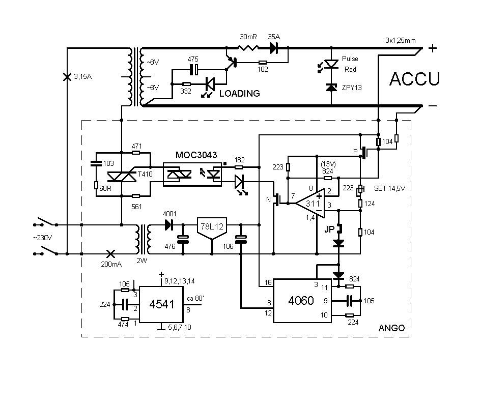
  • The design uses a 15-16VAC transformer, an H4 bulb for current limiting, and MOS protection against short circuits and bad clamp contact.
  • A 45Ah battery rose above 15V and started bubbling after about 3h of charging.
  • The manual setup was unsafe for overnight use because the relay rattled and sparked, and loose clamps could burn out quickly.
AI summary based on the discussion. May contain errors.


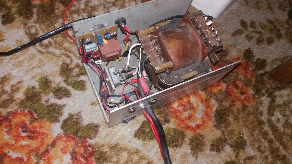
The UPS was sent to the workshop for scrapping. It's a pity for a big case, use the opposite way and it will be a powerful charger.
When once the "joy in the morning" met me for the first time, I thought: let it run for 15 minutes with 20-30A and the car would definitely start and I would make up for being late for work right away.
To work by bus, in the storeroom I found a large transformer with Uo 15-16VAC. Accu plates are not cast, but pressed from Pb powder, a surface charge is formed on them, which penetrates into the volumetric one and is best charged in one-half. Full is 14.44V. A large diode in series with the H4 bulb as a limiting R and short-circuit protection with a clamp, due to the lack of thick 3x1.25mm wires. I connected the makeshift at home, the light bulb turned orange, I checked it from time to time, after m/w 3h the 45Ah accu exceeded 15V and started bubbling.
The bulb indicates but loses power that should go to the accu. In order to leave them safely, e.g. throughout the night, you need an automatic device 13V ON was dropping and the relay was "rattling" and sparking. If the clamps lost contact during charging, they would burn out quickly. This was prevented by the MOS, it also protects the clamps from short circuiting. Charging starts with the accu connection with U < 5V (at least that's what each has) and supports it, doubled with a half + sine wave. In the negative, it supports only U from the accu, so how to disconnect them or make a bad contact charger OFF. The main transformer has a separate fuse, after removing it, you can apply external U to the clamps without fear and set 14.5V, information about the thresholds gives the LED in series with the Optotriac. Jumper would not have to wait for 2 hours until the timer "counts it down" or figure out how to skip it.
Free transformer was great (probably also with microwave but, before I checked it, someone "used" it on Cu) classic and, I suppose, "to save yourself in 15-20 minutes". I shortened the housing with Flex, moved the back panel, etc., and presented the charger to my friend. After a good year (you know, "shoemaker without shoes") I put in such a layoutto yours but with a different timer (out of laziness, simpler printing and 2 times less monsters to drill) and for a triac relay with Ig 10mA, they issued R 1206 in terms of power, but they have a risky small distance between the ends, voltage is better 2010, the most reliable are THT 0.25- 0.6W
The charger came in handy recently when I inadvertently left the car at the parking light. For something else, I needed a pulsating 12V RED diode, it worked from 3V and with Zener "13" from 14.5V. Pulsating informs you that you need to think about a new accu.
BTW. Very sharp "knees" have glass, silver American Zeners, practically nothing below the "knees".


About Author
Xweldog wrote 1202 posts with rating 106 , helped 165 times. Live in city Wroclaw. Been with us since 2008 year.

Comments

tytka 06 Jun 2023 22:03

The device can be practical. But this description; kind of "heavy", not easy to get through it. [Read more]

szymon122 06 Jun 2023 23:26

Charging does not translate to "loading" or at least not related to the battery.. :D What is this strange abbreviation ACCU? If you want a shortcut, write aku. And that's such a weird thing... Overall,... [Read more]

Xweldog 07 Jun 2023 10:37

Szymon122, I am sorry for the discomfort you experienced. I understand you perfectly, I've always had problems with understanding the simplest things, the simpler something the harder it is for me... [Read more]

tomus2k 14 Jun 2023 15:50

Where was that relay that clicked? On alledrogo there is a modular ammeter and voltmeter for ~ PLN 12 I use it instead of the diode and its "loading" system. This gives you a current overview of the... [Read more]

Xweldog 14 Jun 2023 22:51

And you read on? That I replaced it with a triac? Whoever has the time and inclination, let him measure himself as I used to do with the first makeshift. That's why I made an automaton. [Read more]

tomus2k 15 Jun 2023 18:02

Half of the content is taken up by the adventure with the relay, it's worth separating the technical description from the historical one next time. ::Idea And where in my post does it say to replace... [Read more]

Xweldog 12 Jul 2023 17:24

General assumptions for the charger are simple: ON from 0 to 14.5V, OFF 13V etc. At work, a few damaged drivers, etc. with very solid 2W transformers lay fallow. I've never come across a burnt or... [Read more]

W.P. 19 Jul 2023 22:32

If it's a charger, where is the current control? I wonder what whines more after connecting a discharged battery - a transformer loaded with a DC component (one-wave rectification) or a battery. ... [Read more]

Xweldog 20 Jul 2023 09:15

What current control? What for? The first word of the subject is "fast" (implicitly max fast) and at the beginning of the description it is clear why I wanted "from 20-30A". Without control I, the limiter... [Read more]

W.P. 20 Jul 2023 12:43

I wasn't thinking about that. I know you can't power a transformer through a diode, that's every electrician's catechism. I meant loading only one half of the sine wave, which, due to... [Read more]

Xweldog 20 Jul 2023 18:00

Almost every layout can be done in different ways, I bet on 311. If I did it on 358, would you write "it can be done on 311"? [Read more]

W.P. 20 Jul 2023 21:27

No no. I would appreciate a neat design. I recently did a fast charger. [Read more]

Xweldog 21 Jul 2023 11:57

I doubt if it can be easier than 311, in the first approach I had two peers, the second for hysteresis. But, I decided that it doesn't matter if the bottom is 12.8 or, for example, 13.2V, it is enough... [Read more]

W.P. 21 Jul 2023 13:04

Simply, definitely not. I have already cured myself of simple solutions, which resulted in minimization saving 1-2 transistors, several resistors or gates. It made sense in the 1970s and 1980s, hence... [Read more]

FAQ

TL;DR: A recycled UPS can become a 20–30 A fast car battery charger; the core rule is "14.5 V cutoff" with automatic restart near 13 V. This FAQ helps DIY electronics builders reuse a UPS transformer, comparator control, and safe switching for emergency lead-acid charging. [#20660800]

Why it matters: A fast DIY charger can rescue a discharged car battery, but poor switching, weak ventilation, or lost clamp contact can overheat parts and damage contacts.

Option discussed Typical values in the thread Main benefit Main risk
H4 bulb limiter + diode 45 Ah battery exceeded 15 V after about 3 h Simple short-circuit limiting Wastes charging power and can overcharge
LM311 + relay 14.5 V upper threshold, about 13 V restart Simple automatic cutoff Relay rattling and sparking on bad contact
Triac or optotriac switching Ig 10 mA relay-triac version mentioned Less mechanical contact wear Needs correct component spacing and ratings
Modular volt/amp meter About 12 PLN on Allegro Live voltage and current display Adds indication only, not regulation

Key insight: The most important design point is a stable 14.5 V cutoff. The lower restart point can sit around 12.8–13.2 V, but the upper threshold must not drift.

Quick Facts

  • The stated fast-charging goal was 20–30 A for roughly 15 minutes, enough to attempt an emergency start after a flat battery. [#20660800]
  • The prototype used a transformer with about 15–16 VAC open-circuit voltage and a large series diode for half-wave charging. [#20607603]
  • The automatic control concept was: ON from 0 V up to 14.5 V, OFF, then restart around 13 V. [#20651816]
  • A 45 Ah battery exceeded 15 V and started bubbling after about 3 hours on the first crude bulb-and-diode setup. [#20607603]
  • A cheap modular voltmeter and ammeter cost about 12 PLN on Allegro and can replace the simple diode indicator. [#20617068]

How can an old UPS case and transformer be converted into a fast car battery charger?

Reuse the UPS case, transformer, rectifier, cutoff circuit, and heavy output clamps. The thread describes a scrapped UPS with a large housing, shortened by cutting the case and moving the rear panel. A transformer around 15–16 VAC fed a diode-based charger. The target was emergency charging at 20–30 A for 15–20 minutes. Add automatic cutoff, short-circuit protection, and ventilation before regular use. [#20607603]

What charging thresholds should be used for a 12 V lead-acid car battery in an automatic fast charger?

Use 14.5 V as the upper cutoff and about 13 V as the restart threshold. The author later summarized the control logic as ON from 0 V to 14.5 V, then OFF, with restart near 13 V. He also noted that 12.8 V or 13.2 V is acceptable for the lower point. The upper 14.5 V point needs the best stability. [#20662303]

Why did the relay in the LM311 charger circuit rattle and spark when the battery clamps lost contact?

The relay rattled because the unloaded charger crossed its thresholds repeatedly. With no battery load, voltage jumped above 13 V, dropped below 14.5 V, and cycled the relay. Bad clamp contact during charging would make the contacts spark and burn quickly. This failure drove the move toward MOS protection and later triac-based switching. [#20607603]

How does replacing a relay with a triac or optotriac improve an automatic battery charger?

A triac or optotriac reduces mechanical contact problems by avoiding relay chatter at the main switching point. The author replaced the relay approach after observing rattling and sparking. He mentioned a triac relay with Ig 10 mA and warned that 1206 resistors had risky end-to-end spacing. He preferred 2010 parts for voltage spacing or 0.25–0.6 W THT resistors. [#20607603]

What is an LM311 comparator and how is it used to switch a car battery charger on and off?

An LM311 compares battery voltage with a set threshold and drives the charger control. "LM311 comparator is an analog voltage comparator that switches its output when one input crosses another, useful here for detecting 14.5 V cutoff and lower restart voltage." The circuit used one threshold for cutoff and hysteresis for restart. The relay coil version could draw about 30 mA, affecting thermal stability. [#20651816]

What is a Zener diode knee and why did Xweldog mention glass silver American Zeners?

A Zener knee is the sharp voltage transition where the diode begins strong reverse conduction. "Zener diode knee is the breakdown region that clamps voltage, with sharper knees giving cleaner threshold behavior and lower leakage below the clamp voltage." The author mentioned glass, silver American Zeners because they had very sharp knees and almost no conduction below that point. [#20607603]

What is a lead-acid battery surface charge and why does battery voltage drop slowly after charging stops?

Surface charge is temporary charge on battery plates after charging stops. "Lead-acid surface charge is a temporary plate-surface voltage effect that remains after charging, then gradually redistributes into the battery volume and lowers terminal voltage." The author observed voltage falling slowly to about 12.8 V over 0.5–1 hour after OFF. Short top-up cycles then lasted only several seconds. [#20617068]

Where should the relay or switching element be placed in a fast battery charger circuit?

Place the switching element where it interrupts charger output without leaving clamps dangerously live. The thread moved from relay switching to MOS protection and triac switching because clamp loss caused arcing. A separate transformer fuse allowed external voltage at the clamps for setting 14.5 V safely. The LED in series with the optotriac indicated threshold behavior during setup. [#20607603]

How can a cheap modular voltmeter and ammeter from Allegro be added to a DIY battery charger?

Add the modular voltmeter and ammeter as a live charging display, not as the automatic controller. One commenter reported using an Allegro module costing about 12 PLN instead of the diode indicator circuit. The display gives current voltage and charging-current overview. It does not replace the cutoff logic, short-circuit protection, or transformer thermal checks. [#20617068]

Single diode vs bridge rectifier β€” which is better for a high-current car battery charger using a transformer?

A bridge rectifier gives symmetric transformer loading, while a single diode keeps the charger simpler. The discussion compared one half-wave diode with a bridge. One commenter argued a bridge would dissipate 4 times more diode heat, but could mount on a ribbed heatsink near a fan. He also argued it could reduce transformer heating caused by half-wave loading. [#20661050]

Why can half-wave rectification heat a transformer more than expected when charging a discharged battery?

Half-wave rectification loads only one half of the sine wave and can push the transformer core toward saturation. One commenter described the shifted operating point on the magnetization curve during high current charging. A discharged battery draws large initial current, stated as tens of amperes. That heat is hard to remove from the transformer body. [#20661050]

How should current limiting or short-circuit protection be handled in a fast 20–30 A car battery charger?

Use protection that limits clamp short-circuit current without wasting normal charging power. The first prototype used an H4 bulb as a limiting resistor and short-circuit protector. The author later viewed current regulation as unnecessary for a maximum-fast 20–30 A charger. He still kept short-circuit protection for clamps and treated it as separate from charging-current control. [#20660800]

How can ventilation be improved in a DIY charger when shunt resistors or milliohm resistors get hot?

Increase airflow and clearance around hot resistors, then verify plastic parts stay cool. The author found a milliohm resistor had almost melted a plastic bracket 2 cm away. His own charger used 1 cm legs and many drilled ventilation holes in the top and bottom. He planned more holes in the UPS lid after adding a relay-thyristor board. [#20651816]

LM311 vs LM358 vs LM393 with TL431 β€” which circuit is better for stable battery charger voltage thresholds?

LM393 or LM358 with a TL431 can make separate thresholds easier, but LM311 keeps the circuit simpler. One commenter proposed two operational amplifiers or comparators, each with its own threshold. He suggested an LM431 or TL431-style stabilized reference for better thermal stability. The author preferred LM311 and adjusted the circuit so the important 14.5 V threshold stayed resistor-defined. [#20661050]

How do you safely set and test the 14.5 V cutoff voltage in an automatic car battery charger?

Set 14.5 V with the main transformer fuse removed and an external voltage applied to the clamps. 1. Remove the transformer fuse. 2. Apply external adjustable voltage to the clamps. 3. Adjust the trimmer until the LED and optotriac indicate the cutoff threshold. This avoids waiting about 2 hours for the timer and reduces risk during setup. [#20607603]
AI summary based on the discussion. May contain errors.
%}