Simple AM/FM radio - Lowry - CD2003GP and D2822A - SC3610D connectable
 .
.
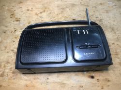
Some time ago I showed the Fonics FN-105 radio, which turned out to be based on the CD7613CP chip, a so-called 'one-chip radio'. It even had an audio amplifier in it. Now it is time for another similar radio, but this time built slightly differently. We will look inside and analyse the PCB.
Previous related topic in the series: Fonics FN-105 - CD7613CP .
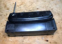
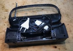
This radio also belongs to a friend from the allotments and it too has this distinctive modification with a switch on the cable. The friend must like these switches. You can get quite a surprise when you open the battery slot:
 .
.
Who would have expected:
 .
.
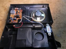
Removing the case, inside is the speaker, one PCB and the mains transformer:
 .
.
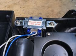
Interestingly, the transformer has a built-in thermal fuse:
 .
.
I wonder how effective it is.
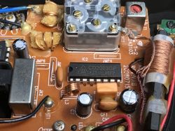
Now the PCB itself, the layout is even simpler than before, apart from the obvious presence of a ferrite antenna and an adjustable capacitor used for tuning, here we have a headphone socket, a couple of properly protected air-core coils and this time two chips: CD2003GP and D2822A
 .
.
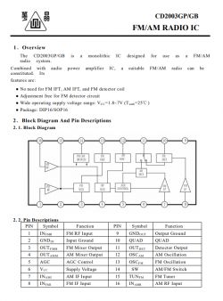
Catalogue note:
 .
.
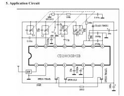
Example application diagram:
 .
.
I think I even know this schematic from somewhere, haven't I done a DIY like this before? But let's not forget the D2822A amplifier (looks similar TDA2822M?):
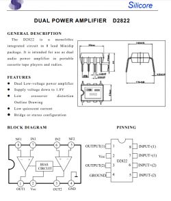 .
.
This die can be used in both mono and stereo applications:
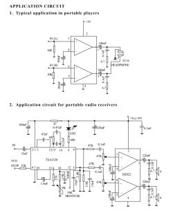 .
.
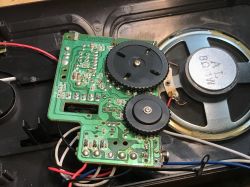
Another look at the underside of the PCB - there are some SMD components here, this explains why the board is slightly smaller than I would have expected. The rectifier diodes are also surface mounted.
 .
.
By the way, the diodes are three and have small ceramic capacitors in parallel.... one of them probably protects the batteries, so either from the transformer there must be a single pole rectifier or the transformer is tapped?
Judging by the fact that only two of the diodes have a capacitor, I would bet that there is a transformer with a split secondary winding....
And I think that's it - there's one more photo of the whole PCB left:
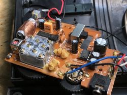 .
.
Summary .
This is interesting, the previously described Fonics FN-105 was based on a single chip, the CD7613CP, and had no SMD components, here they have introduced a bit of SMD already, but the amplifier and radio circuit are separate.
The CD2003 used here is a classic, and I have seen DIY projects/kits to assemble on it, including even a project with a frequency display:
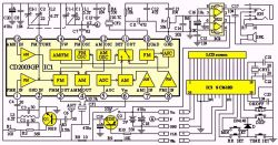 .
.
Here the SC3610D is used in conjunction with the CD2003. If you are interested, you can look for this kit to buy online, although I would rather be tempted to DIY modify a ready-made radio.... maybe it would be possible to buy an SC3610D, only probably worse in terms of cost, all of which would make it just art for art's sake.
Alternatively, you could always just buy a ready-made FM Radio Kit and put it together, maybe some readers have played around like that? From what I remember, I once assembled a simple radio myself, also on a ready-made IC, only now I can't remember if it was a CD2003 or another one...


Comments
This time you've come across better grade equipment. On the board you can see two ceramic filters and a resonator. These contribute to the better selectivity of the radio. Transformer with split winding... [Read more]
I was always puzzled by those sponges in the air coils that were barely saturated with paraffin. Nowadays FM UKF and DAB+ have taken over radio broadcasting in Poland, long wave broadcasts I, there... [Read more]
The sponge served as a kind of "filler" - thanks to it, less stearin(paraffin/wax) could be used (depends on the stage/year of production) and it also held the sealant inside the coil. This made the coil... [Read more]
About 10 years ago, when "Everything's 3 zloty each" except what's five 😉 in the shops, you could buy various models of miniature UKF FM receivers that searched for stations by scanning the band up and... [Read more]
I've come across the CD2003 a couple of times and even have one (from the outlet). Quite popular in Chinese radios. Greetings, A. [Read more]
https://obrazki.elektroda.pl/9017262100_1692139039_thumb.jpg https://obrazki.elektroda.pl/9912059300_1692139059_thumb.jpg . This is what the first one looks like and the second is a Bench from... [Read more]
. I have a couple of NE612's from the cast-off, I think I even described their recovery in one of my disassemblies of an old SAT tuner. Interestingly I also have a TDA2030, UA741 I think. Maybe in my... [Read more]
Why is the pass band of this receiver 10 kHz when the audio bandwidth is anyway limited to max. 4.5 kHz due to the 9kHz raster? [Read more]
. I would approach this design with caution, there are a lot of coils, 7x7 inductive filters produced back in communist times that are now hard to acquire. There is no resonator or ceramic filter, including... [Read more]
@pkaczmarek2 great! I would rather dispense with the UA741 in favour of newer versions of the operational amplifier, I used NE612 in an FM receiver on 2m and it worked fine, You can possibly resign... [Read more]
No exaggeration, you can obtain from dismantling some radio, you can even find with a bit of luck in a dumpster ;) I in any case probably have such filters, diodes different. Greetings, A. [Read more]
A neighbour also threw me a "Sencor SRD 210B" radio on CD 2003 and TDA 2822 chips. The radio is humming, no FM or AM reception. Power supply from 3 x R14 batteries, i.e. 4.5V, and 9.7V from the power... [Read more]
You can, they are on Aliexpress. There are still chips left from disassembly if you don't want to buy there, find a donor or someone who has one. I have one, but I don't know if it's working. Another... [Read more]
There are 2 offers on the web for about £10 each + postage. In my shop they demand 32 zł. What about the voltage from the 9.7V power supply? The power supply parameters for this circuit are 1.8-7V. [Read more]
And this is probably the cause. My radio from Lidl has a 6V power supply at idle. [Read more]
. There is no voltage stabiliser or anything to lower this voltage? Greetings, A. [Read more]
There is no stabiliser (you will have to insert one). There are only two diodes in parallel ( track side) and a capacitor in the power supply. https://obrazki.elektroda.pl/9684376000_1702229265_thumb.jpg... [Read more]
Capacitors worth reviewing Are you sure these diodes are in parallel? I would rather bet on a two diode rectifier here. Regards, A. [Read more]
You can even see in the photo - the two blue cables are AC and the black is GND. Trafko with split winding. [Read more]