Radio from the kitchen of communist Poland - Unitra, Ludwik DMT-408 - gallery, interior, diagram
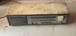 .
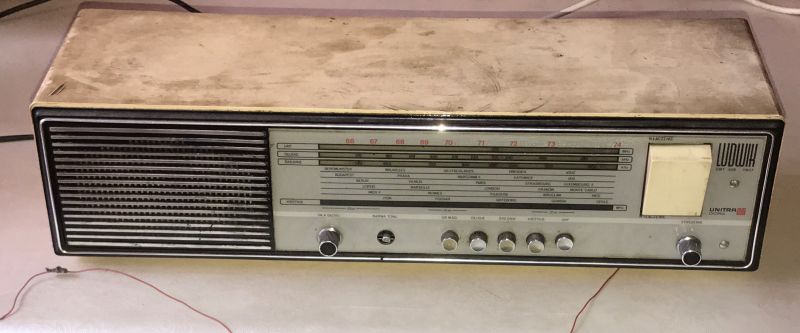
.I would like to invite you to another topic about an old Polish radio receiver, this time about a Ludwik from the 1970s, characterised by a large rocker On/Off button on the right side of the front of the case. This receiver allows you to listen to four ranges, standard long wave, medium wave, short wave and ultra short wave, whereby to listen to something in our time you would have to tune out the UKF, but to start with a look at the casing:
 .
.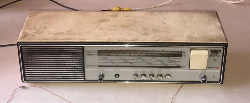
On the front, in addition to the range selector and volume control, we also have a tone knob and the option to switch to the tape deck connector.
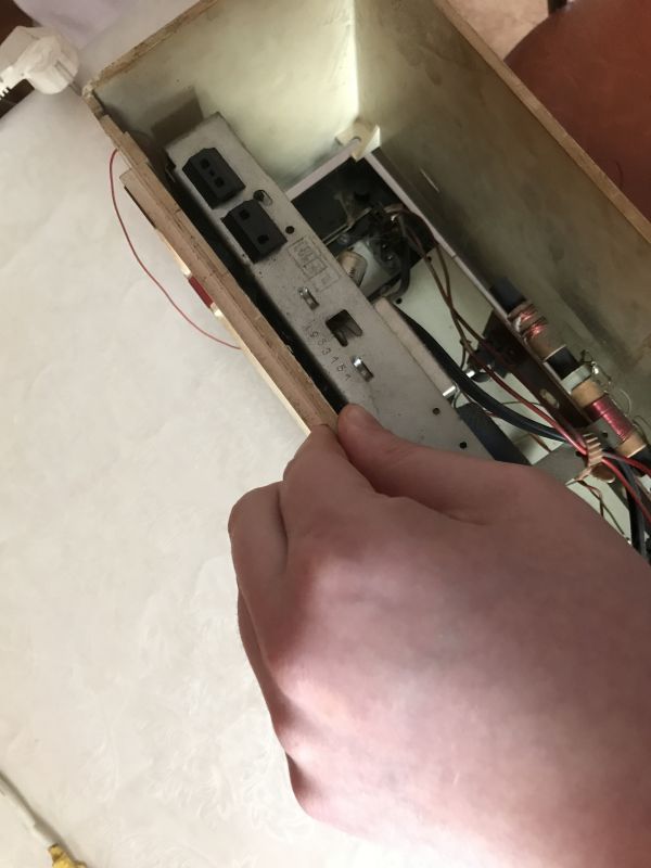 .
.On the back we have a cassette connector, a connector for the aerial, in my case unfortunately the back cover is missing.
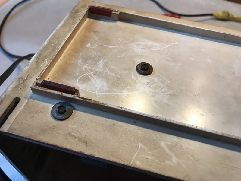
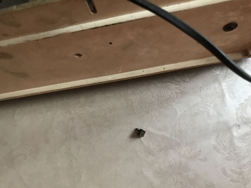 .
.After freeing the PCB and separately the mains transformer, the front with the electronics can be slid out.
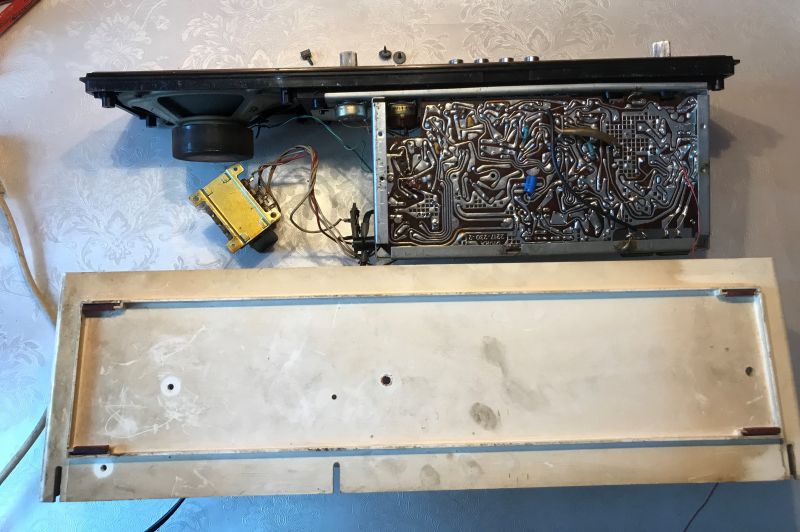
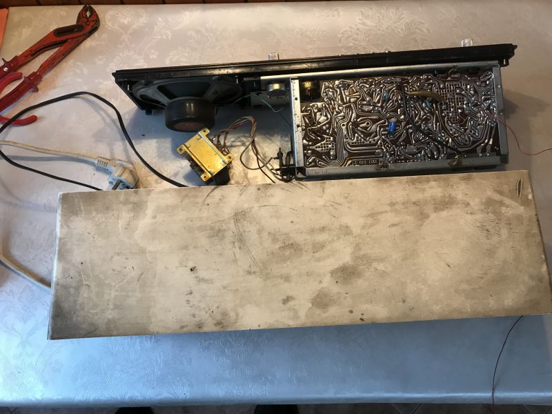
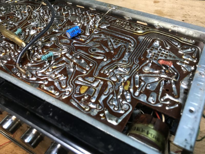
The plate is characteristic of the time, single layer, the tracks still guided by hand:
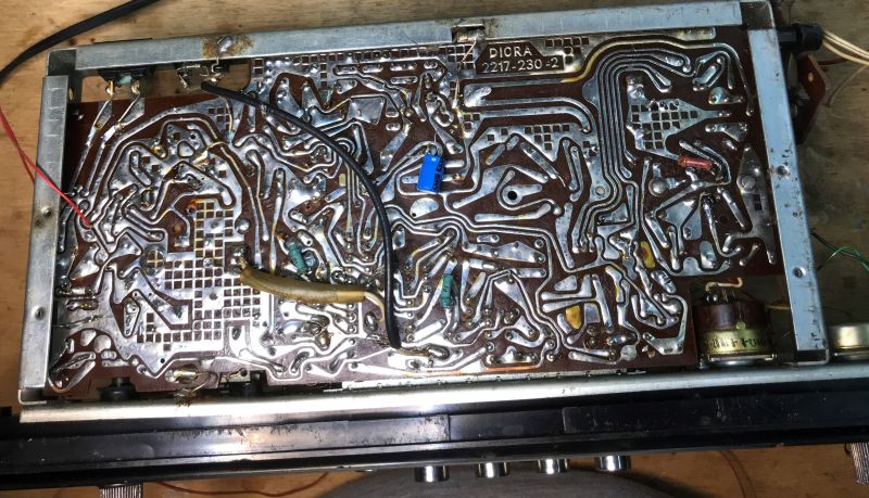 .
.These individual components mounted on the underside are, I don't know at the moment whether this is the user's invention or whether it was manufactured as such?
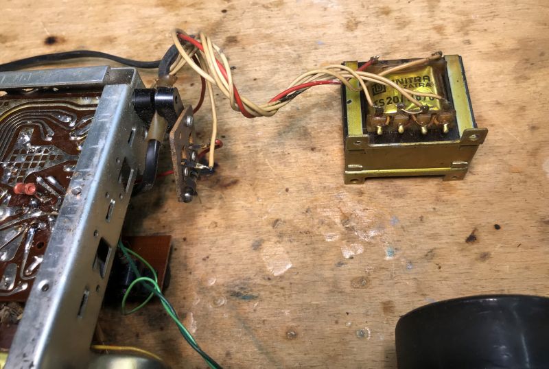
The transformer is an ordinary 50Hz mains transformer, Unitra Zatra:
 .
.The ferrite antenna is conspicuous inside, and there are traces of tampering:
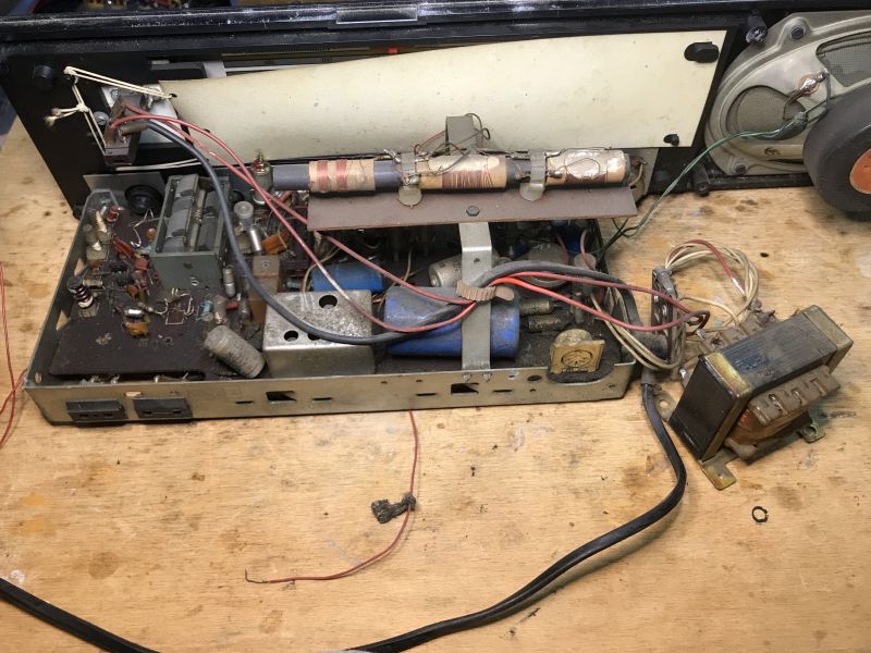
Here you can see the adjustable capacitor, it is the one that implements the tuning by changing the capacitance.
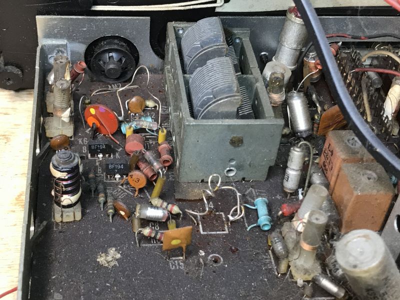
Someone must have made an attempt at tuning, with better or worse results.
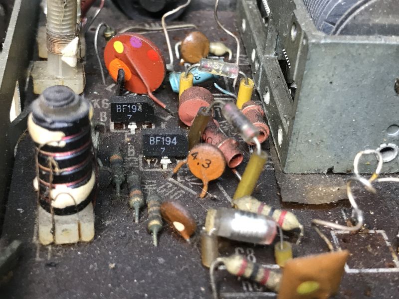
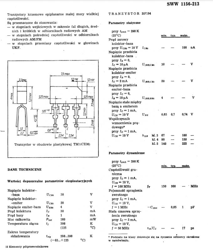
The photo above shows two low-power, high-frequency BF194 silicon transistors typical of the time:
 .
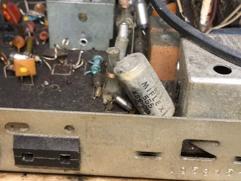
.Miflex capacitor, with the results of someone else's games in the background:
Coupled Isostat switches:
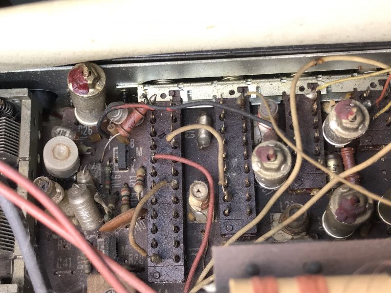
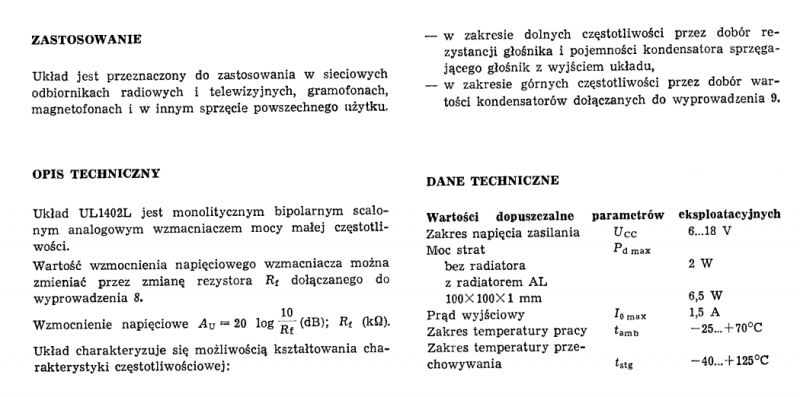
Below the UL1402 circuit:
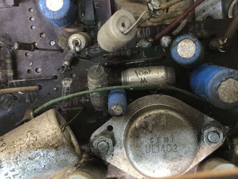 .
.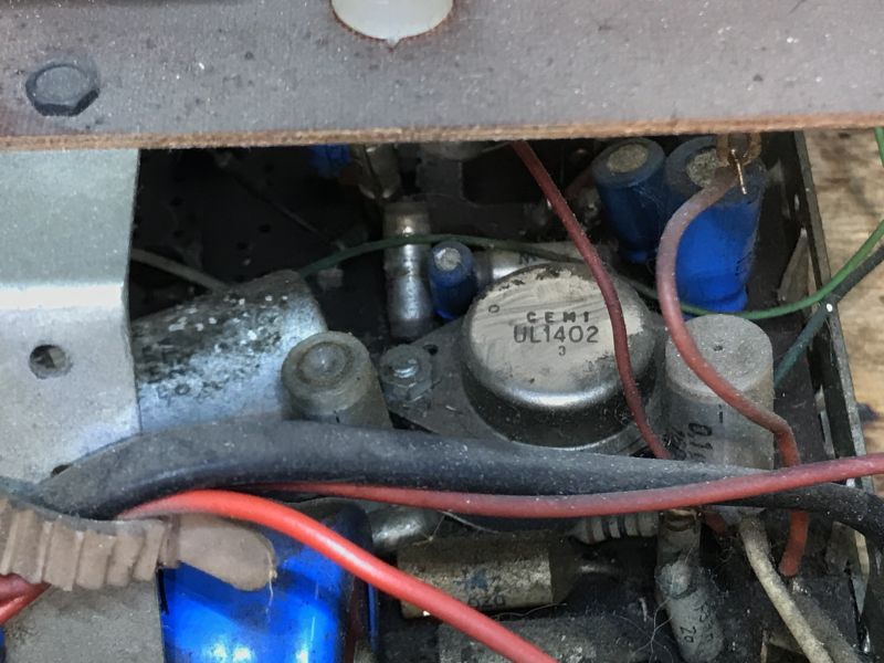 .
.The UL1402 is a low power amplifier:
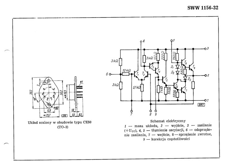
 .
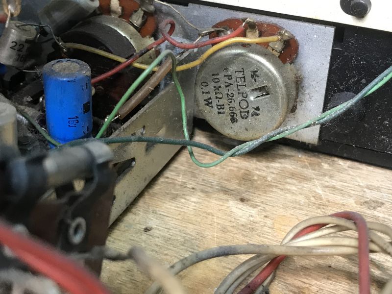
.Telpod 10 kΩ 0.1 W potentiometer:
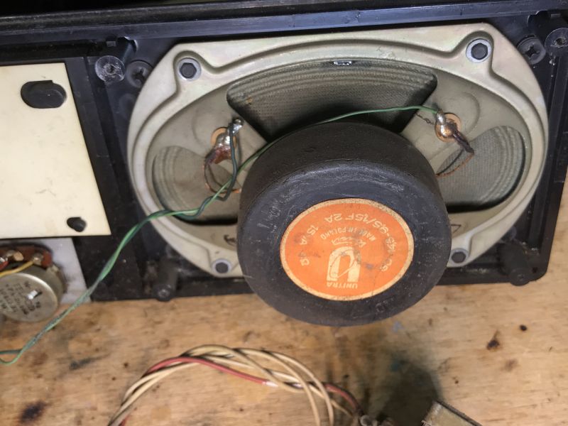
Below, a speaker with the proud inscription Unitra - Made in Poland:
 .
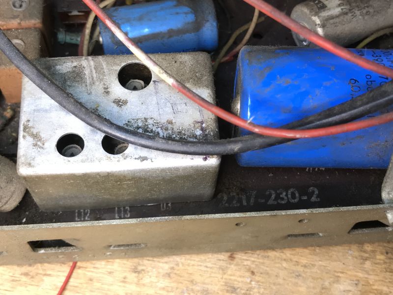
.Shielded part of the circuit:
 .
.And the connectors:
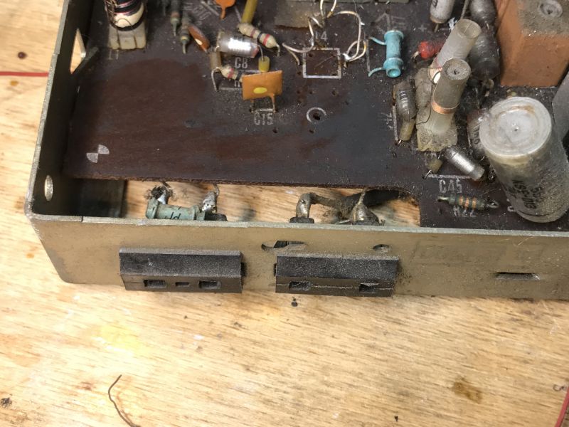 .
.Finally, a diagram:
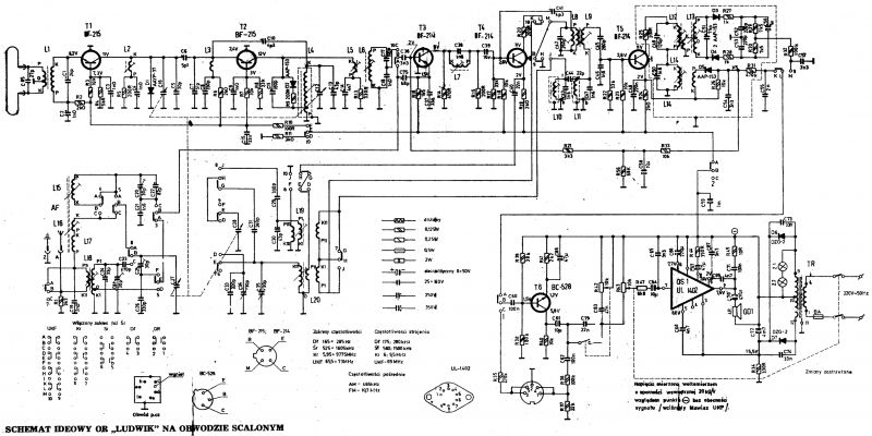 .
.The diagram above shows the Ludwig DMT-408 (1974), where the m.c. amplifier is based on the UL1402. There was also an earlier version, the DMT-405, where this was implemented on transistors (1972).
Summary .
It's a wonder I didn't know of the existence of this Unitra receiver before. Its unusual style really catches the eye. I wonder what it looked like in its heyday, in its "natural" environment. I simply have no way of remembering it myself, I can only know it from stories. It's a pity that it has already been hit without the back panel. From what I've seen in pictures online, this panel is also pure retro.
Does anyone have this type of receiver in their collection as well? Feel free to comment and post photos of your specimens.


Comments
A fine old piece of equipment. I see someone has been tinkering with it before. [Read more]
Whether it's so noble I don't know. It looks like a "family" to Adam and Gong. Of which I would definitely prefer the aforementioned two. [Read more]
I hope that the author and the administrator will forgive me a bit of offtopic, but the topic brings together lovers of such radios, so the soonest someone will be interested here. Two radios of a similar... [Read more]
@pkaczmarek2 a few radios of this type have passed through my life, but I haven't seen this one yet. Is the case wooden or bakielite? If wooden then there is no veneer on it. The unit, or air capacitor,... [Read more]
. Both of these connectors are used to connect antennas. I am posting a photo, from the first post, with the connector used to connect the tape recorder marked with a red border. https://obrazki.elektroda.pl/1800806100_1694441729_thumb.jpg... [Read more]
. These may have already been factory "tweaks". Well maybe apart from that capacitor connected to the UL1402 legs. The UL1402 itself looks like it has probably also already been replaced looking at the... [Read more]
You can see by the design that this is quite a vintage receiver, but complete and without significant damage. Something between the older tube ones from the 1960s and the newer ones from the late 1980s. It's... [Read more]
It is probably no longer worth resuscitating this unit. The casing is plastic, of poor quality and in very poor condition. The radio itself has rather low sensitivity and, above all, poor FM selectivity.... [Read more]
@pkaczmarek2 the backs I used to make up, but it is labour intensive and tedious work, but it was worth it. [Read more]
. Well. Because most of these types of radio receivers from "those days" were made on principle in this respect: Copy, paste. Well, maybe some insignificant changes in the form of changing capacitance,... [Read more]
. The fact that the ranges are there is unlikely to help, as selectivity on the shortwave range is very poor for this type of radio. In the Tambourine there were 4 p.h. transistors simultaneously working... [Read more]
. You're wrong. Try, when you are in Gdansk, to pick up with such a receiver e.g. Antyradio, which transmits on 92MHz while right next door on 92.3MHz Radio Kaszebe is broadcasting. With a good receiver,... [Read more]
This affliction to fail for no reason generally goes. I've seen some people take it a step further and insert a noval tube socket, which just so happens to have the perfect spacing as the UL140x. The... [Read more]
. At shortwave this is the 40 to 31 m range, a band of just over 2 MHz. . If there was a carcass then there was also a threaded core, which determined the inductance as much as the number of turns. And... [Read more]
. Well bandwidth is bandwidth and selectivity is selectivity. On the Tambourine the sensitivity is satisfactory, but because of the low selectivity there is no way to get decent reception. Stations... [Read more]
. For the sake of clarity, stations on KF gently "float" not because of heterodyne instability but mainly because of wave reflections from the ionosphere. These reflections cause changes in signal level... [Read more]
I used to have such a radio (maybe it's still standing at my parents' house?) in a transistor-based version. As far as I remember the power amplifier was made on a germanium complementary pair of AC s... [Read more]
A piece of history. I have had this receiver serviced. It was in better condition and is in very good condition. Those who are interested are invited to visit my channel on YT. I applaud the author for... [Read more]
@zpasjadounitry Great videos you have on the channel. Thanks. :) [Read more]