[ESP8266/LM1] LED strip controller with WiFi RGB WS03 - interior, Tasmota, GPIO configuration
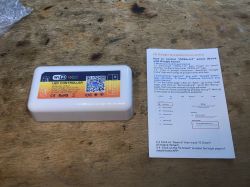
Today we are discussing another LED strip controller from a Polish auction site. This time the RGB version, i.e. intended for colorful LEDs. The controller is intended for the OpenLit mobile application, but we will flash it with Tasmota, as we usually do, in order to free it from the cloud and connect it locally with Home Assistant.
This product was given to me for free by a reader so that I could change his load. After programming, the product was returned to the reader. I received several other pieces of equipment in the set, including the related WF-M2 controller:
https://www.elektroda.pl/rtvforum/topic3992073.html
Purchase of WS03
We bought the product for less than PLN 50, here are some screenshots from the auction:
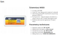
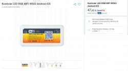
What catches your eye is an unusual mobile application - OpenLit - it is neither Tuya, nor SmartLife, nor even eWeLink, but we don't care because we will change the load anyway.
Let's see what we get in reality. It happened once before with this seller that we ordered WF-M2 and received WF-M4:
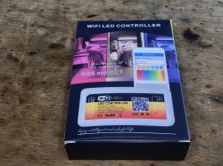
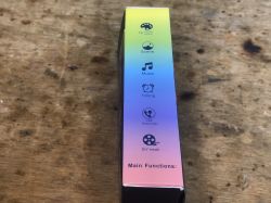
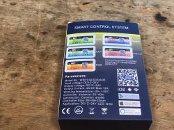
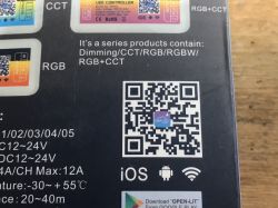
Set contents:
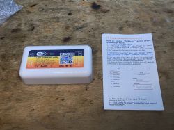
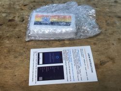
I don't know where "Skills & Game" came from in this manual, but I haven't tested the application. Time to open the controller...
Interior of WS03
We pry the housing with a flat screwdriver. There are no screws here. What's inside:
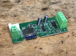
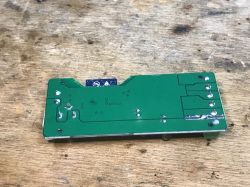
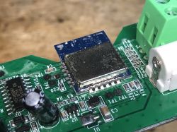
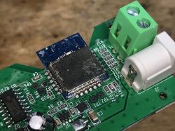
The WiFi module is not signed, but I know it by sight and by the number of pins. It's LM1. So ESP8266:
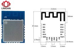
Next we see a very strange structure of this strip, which makes it stand out from what I have seen before:
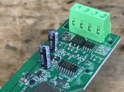
It's supposedly RGB, but instead of three identical transistors we have:
- DTU 09N03S
- WSP4888
Additionally, the MOSFET is controlled by the 74HC4050.
I'll draw it out in a moment, but first the rest of the system:
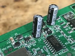
The WiFi module itself, you can also see the step down converter that generates 3.3V from the 12V power supply for the LED strip:
Changing the load
This is an ESP8266, so this has been discussed many times. I'll link some of my old topics:
https://www.elektroda.pl/rtvforum/topic3760371.html
https://www.elektroda.pl/rtvforum/topic3749207.html
esptool.py is enough for me and I always make a copy of the batch and then upload Tasmota.
I have already provided the LM1 pinout.
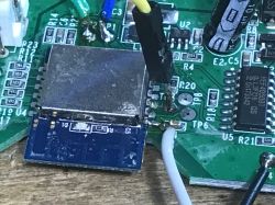
Soldering cables:
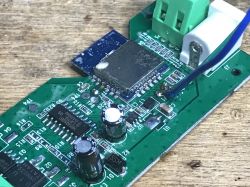
RX, TX, IO0 and power supply (3.3V):
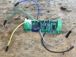
Here I soldered the capacitor from the power supply:
Below is a sketch of the connections. If you have any questions, please contact him:
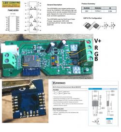
Used GPIO as PWM:
- IO14 - ed
- IO13 - green
- IO12 - blue
Potentially used GPIOs in the RGBCW version:
- IO5 - Q4 (not soldered)
- IO15 - Q1 (not soldered)
There is no button on this PCB.
Summary
The WF-M2 strap controller seemed to be better because it had a button placed on the housing, but the controller discussed here has slightly better transistors. Certainly stronger than the tiny A09T. I don't know why two different versions of transistors were used here (including one "double", two in one housing). This is even more strange because it's an RGB controller, so each channel is completely independent.
There is definitely a choice, we can choose what suits us for a specific application.
It is also worth remembering that after changing the firmware, adding a button is very simple. This can be easily configured in Tasmota. You just need to cleverly solder it to the PCB and drill a hole for it in the housing. Moreover, not only the button - even DHT11 or another thermometer etc. can be additionally connected and configured to receive measurements in Home Assistant. Then you just have to remember not to close the sensor together with the transistors, because then the transistors would heat up and distort our measurements... In any case, the possibilities after changing the firmware are very large.


Comments