[BK7231N - CBU] Teardown of Aldi (Australia) CasaLux Smart Led Corner Lamp
I got a couple of Aldi (Australia) CasaLux Corner Lamps.
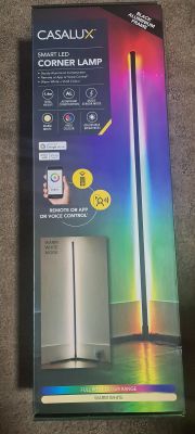
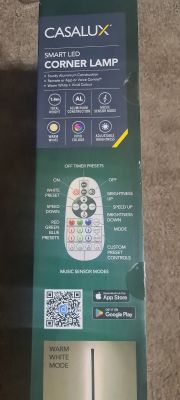
There is no product URL that I can find anymore but the box looks like this:
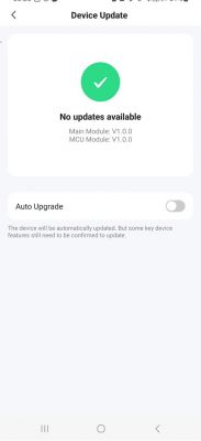
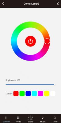
After I added it to Tuya app this is what options are in it:
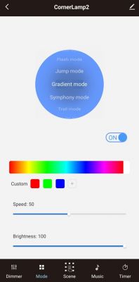
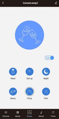
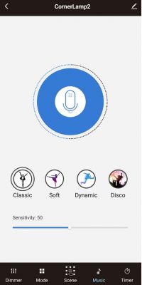
The DP Ids I have found in Tuya IoT are:
When turned on this is how the device works:
After opening a few screws from the base I got to the PCB:
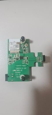
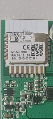
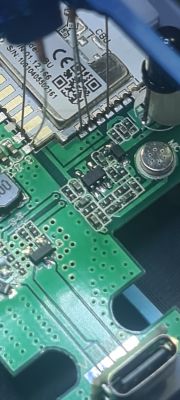
And there is a CBU module:
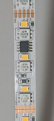
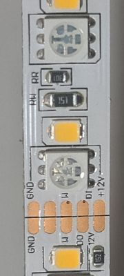
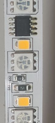
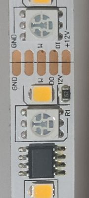
Below are some pics of the led strip used in this device:
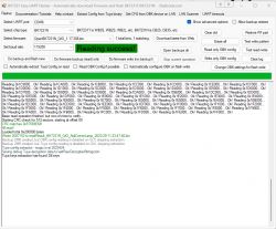
Next got my hacking kit out and got a Tuya firmware backup (attached):
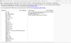
OBK configuration extraction did not reveal anything useful - must be TuyaMCU in there somewhere
I have not flashed OBK to it yet.
Just wanted to see first what is possible to do with this device.
@pkaczmarek2 - again looking for your guidance to see how I can config this device with OBK.
There is no product URL that I can find anymore but the box looks like this:


After I added it to Tuya app this is what options are in it:


The DP Ids I have found in Tuya IoT are:
{
  "result": {
    "properties": [
      {
        "code": "switch_led",
        "custom_name": "",
        "dp_id": 20,
        "time": 1701165459278,
        "value": false
      },
      {
        "code": "work_mode",
        "custom_name": "",
        "dp_id": 21,
        "time": 1701163432151,
        "value": "dynamic_mod"
      },
      {
        "code": "colour_data",
        "custom_name": "",
        "dp_id": 24,
        "time": 1696248937973,
        "value": "003d03d40386"
      },
      {
        "code": "control_data",
        "custom_name": "",
        "dp_id": 28,
        "time": 1696232883464,
        "value": ""
      },
      {
        "code": "music",
        "custom_name": "",
        "dp_id": 102,
        "time": 1696247788543,
        "value": "424"
      },
      {
        "code": "RGB_order",
        "custom_name": "",
        "dp_id": 103,
        "time": 1701163432162,
        "value": 1
      },
      {
        "code": "LED_QTY",
        "custom_name": "",
        "dp_id": 104,
        "time": 1701163432172,
        "value": 30
      },
      {
        "code": "dynamic_mod",
        "custom_name": "",
        "dp_id": 106,
        "time": 1701163432151,
        "value": "043263000003e803e8007803e803e800f003e803e8"
      },
      {
        "code": "scene_mod",
        "custom_name": "",
        "dp_id": 108,
        "time": 1696247502001,
        "value": "CJ_YS"
      }
    ]
  },
  "success": true,
  "t": 1701276246105,
  "tid": "829cbbd58ed611ee83c62e7e80387ed3"
}
When turned on this is how the device works:
After opening a few screws from the base I got to the PCB:

And there is a CBU module:

Below are some pics of the led strip used in this device:


Next got my hacking kit out and got a Tuya firmware backup (attached):


OBK configuration extraction did not reveal anything useful - must be TuyaMCU in there somewhere

{
	"abi":"0",
	"id":"null",
	"swv":"1.0.0",
	"bv":"40.00",
	"pv":"2.2",
	"lpv":"3.3",
	"pk":"didby1zofoliihp5",
	"firmk":"null",
	"cadv":"1.0.4",
	"cdv":"1.0.0",
	"dev_swv":"1.0.0",
	"s_id":"null",
	"dtp":"0",
	"sync":"0",
	"attr_num":"1",
	"mst_tp_0":"9",
	"mst_ver_0":"1.0.0",
	"mst_tp_1":"0",
	"mst_ver_1":"null",
	"mst_tp_2":"0",
	"mst_ver_2":"null",
	"mst_tp_3":"0",
	"mst_ver_3":"null }`)LAgw_wsm3&WAwf_start_mdll",
	"md":"0",
	"random":"0",
	"wfb64":"1",
	"stat":"0",
	"token":"null",
	"region":"null",
	"reg_key":"null",
	"dns_prio":"03{nc_tp",
	"ssid":"null",
	"passwd":"null",
	"ap_passwd":"null",
	"country_code":"null",
	"bt_mac":"null",
	"bt_hid":"null",
	"prod_test":"false",
	"fac_pin":"mzlyh8vz7p33qbz9 "
}
Sorry, no meaningful pins data found. This device may be TuyaMCU or a custom one with no Tuya config data.
No module information found.
And the Tuya section starts, as usual, at 2023424
I have not flashed OBK to it yet.
Just wanted to see first what is possible to do with this device.
@pkaczmarek2 - again looking for your guidance to see how I can config this device with OBK.


Comments
Hello, can you check where is the data signal of LEDs connected? I think it may be connected to P16, which means there is a WIFI module driving LEDs directly, without TuyaMCU. Check Tuya docs to see where... [Read more]
The data pin seems to go into the unmarked black chip. Not sure if it goes to P16 (marked in red which actually is RX1) from there. https://obrazki.elektroda.pl/3997244000_1701278465_thumb.jpg ... [Read more]
You have marked RX, not P16. There is a difference between pin 16 on image and P16 of BK: P16 (SPI_MOSI) used to control LEDs directly is a pin 2 on the CBU image. https://obrazki.elektroda.pl/... [Read more]
I see what you mean - my bad There seems to be a trace coming out of P16: https://obrazki.elektroda.pl/4514204600_1701279587_thumb.jpg Seems to be going to the black chip under HR1 [Read more]
This is RGB + W device, right? So RGB LEDs are addressable and W is driven via PWM? [Read more]
RGB LEDs are addressable. But not sure if W is PWM - how can I tell? The device is still hooked up - if you think there is something to work on I can flash it to OBK. I have a tuya backup as a last... [Read more]
Does the brightness of all white LED always change together? Or can it display different brightness levels per LED? I don't know if OBK supports it, I think we can do some short tests and then restore... [Read more]
As attached to the original post - I think I have the correct back up? https://obrazki.elektroda.pl/7394011900_1701280755_thumb.jpg [Read more]
It seems correct, you can try to flash OBK and for a good start play with GPIO doctor, maybe one of the pins is a simple PWM to control white level. There is 6 available PWMs on CBU, so there is not... [Read more]
OK will do. I tried to dim the white light via Tuya app and all whites dimmed together. We will see what happens in OBK next :) BTW - so you dont end up waiting for me - Ill flash it and go to bed.... [Read more]
Once we finish testing with the GPIO doctor, we will also proceed to test the LEDs with current SM16703 driver. I tested it with WS2812 once, and it was somewhat working, but it wasn't perfect. [Read more]
GPIO Doctor shows that PIN6 = PWM. It controls the white color. https://obrazki.elektroda.pl/8478829600_1701304234_thumb.jpg Toggle and brightness work fine. [Read more]
Ok, now try: 1. Start driver startDriver SM16703P 2. Init Driver - replace 64 with number of LEds SM16703P_Init 64 3. Set Pixel SM16703P_SetPixel 1 255 0 0 SM16703P_SetPixel 2 0 255 0 SM16703P_SetPixel... [Read more]
OK, I get this: https://obrazki.elektroda.pl/9989825700_1701305873_thumb.jpg The first 3 LEDs are cool white. The second lot of 3 LEDs are RED. The third lot of LEDs are GREEN. The fourth lot of... [Read more]
You can try script from this post: https://www.elektroda.com/rtvforum/viewtopic.php?p=20734037#20734037 So the proof of concept works... [Read more]
OK, if I add that code below to autoexec.bat, I restart the device and nothing happens. I think I am doing something wrong. setChannel 10 1 again: addChannel 10 1 SM16703P_SetPixel $CH10-2 0 0 255 SM16703P_SetPixel... [Read more]
@pkaczmarek2 - Would you have some time to see if we can progress the work on this? Cheers :) [Read more]
I will try to look into it soon, but today I am finishing RN8209C driver: https://www.elektroda.com/rtvforum/viewtopic.php?p=20840241#20840241 On your side, I will most likely first do that CW/RGB separation... [Read more]
Hi @pkaczmarek2 - any progress on this yet? [Read more]