Today`s mini-project is perfect as training material for young electronics students.
Before Christmas, I was asked to make a simple Christmas tree decoration. Among many possibilities, I chose the floating light effect. It can be observed in "ignicle lights" on Christmas trees at Christmas fairs, in new luxury cars (floating indicators), or in the form of light floating in a circle (an interesting application is e.g. a bicycle rear light). It should be noted that this is not a shining running point, but a gradually lit line of light, which in the second phase gradually goes out, giving the effect of a wider moving light.
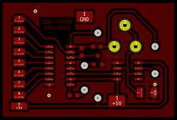

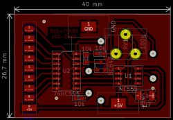
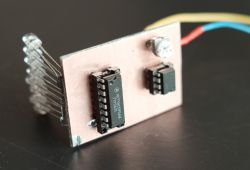
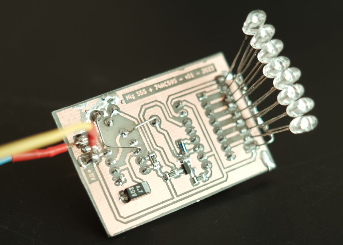
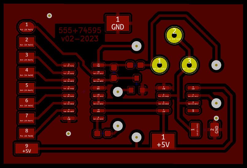
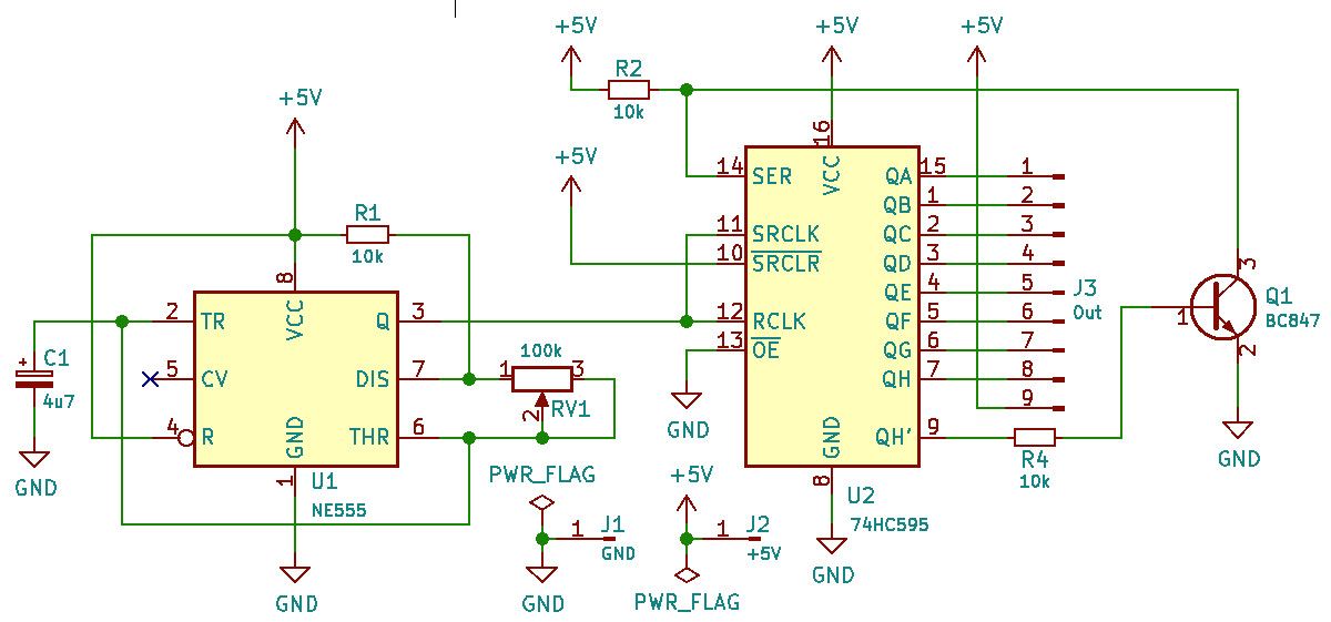
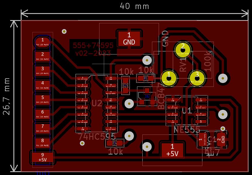
In this mini-project, I present a scheme proven in practice (there are usually various "interesting" errors on the Internet - I have been trying to combat this thoughtless practice for years), a single-sided PCB (in SMD technology) and the arrangement of elements. In my case, I power the system with a single Li-Ion 18650 cell with an attached charge/discharge control module (of course, the diagram does not take this into account, I use a known module with a nominal value of PLN 1-2).
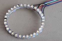
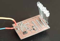
As you can see, there are no LEDs on the PCB, I made this glowing ring (in my case) in a three-dimensional form, using an idea from YT (just enter the phrase "74HC595 LED chaser"). On the PCB we have 8 outputs for cathodes and plus power supply for a common anode (in my case it is in the form of a circle made of thicker copper wire). When powered by one Li-Ion cell, LED resistors are unnecessary. It is worth adding that we can divide such a circle into 2 or 4 parts and solder 8 LEDs in each section. The potentiometer (peer) is used to change the speed of the effect.
By the way, here`s a tip to help you make a nice circle with LEDs. First, we draw a circle, divide it into 8, 16 or 32 parts and mark the points for drilling 5mm holes. Then we stick our sketch on a piece of board, drill for a few minutes and we have a perfect template. Such help allows you to make many copies of the system in a repeatable way.

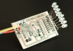
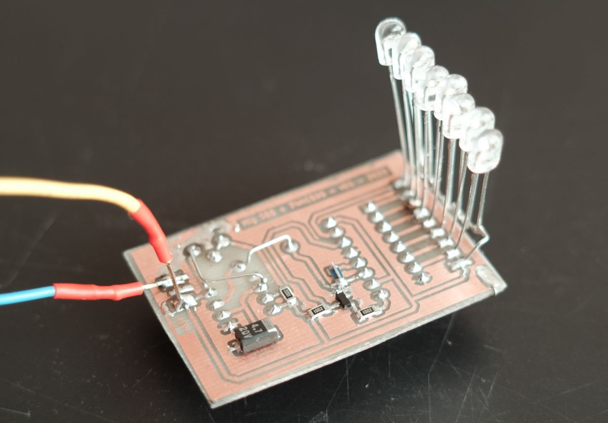
Here you can see the first, prototype version of THT (I still had to make a few minor corrections here, as can be seen in the title photo). This is basically the finished "floating turn signal":
A short video showing the achieved lighting effect:
I recommend it to everyone learning the difficult art of soldering, such a system does not require complicated startup and should bring satisfaction


Comments
Gadgets for points LED Christmas tree 5V kit for assembly [045] Ready. [Read more]
Wouldn t know that this kit was in gadgets. Although here we have greater creative possibilities. I ll understand :-) [Read more]
And yes, you can. Start by digging out copper in the mine, silicon in the deposit... A smoke machine would probably come in handy as well. [Read more]
1) @trojan12 : post #2 thanks for the tip/info about Gazeta! 2) post #4 Why do you mock/discourage independence? walking this way- ` What for to learn addition/multiply/integration?!? ... [Read more]
And I personally appreciate such work. Satisfaction with the built devices, even the simplest ones, is priceless, in the full sense of the word. If someone wants to be a real electronics designer, he or... [Read more]
I support my friend yogi009 and rafi8112 here Some of us certainly remember the times when we had even "color" TV sets (Neptune). There was enthusiasm and pressure for various structures. Fighting and... [Read more]
I added some pictures and a short video to the title post. [Read more]
I know that it t you protect the PCB with a soldermask after milling? [Read more]
It`s nice to build something sometimes and think about how to do it without a microcontroller, we should have an order to build every third project without a microcontroller. All the knowledge from years... [Read more]
Because this is the first training prototype (made in THT), I ultimately made the second version in SMD and this one was treated with varnish for electronic boards. I don t intend to buy it wholesale and... [Read more]
Hello You can do without 555, just use a generator on bipolar transistors. In the retro version, you can use a counter, e.g.: 7490, and a BCD decoder, e.g.: 74145. This is how bells - music boxes... [Read more]
Of course. It`s a matter of choice. [Read more]
Cool project! What program did you use to design the printed circuit board? Once upon a time, as a young boy, it was a lot :P I soldered things like that. But some time ago, as a reminder of the old times,... [Read more]
KiCad :-) [Read more]
I used to draw some simple circuits in KiCad, but I didn`t design the board itself. How do you rate the friendliness of the user interface and reducing the risk of errors? Is there any control? [Read more]
I switched to KiCad when Eagle was bought by Altium and the subscription was introduced. KiCad has a slightly different way of flowing information, there are simply further steps that need to be followed.... [Read more]
I have to check it out when I have some free time... :) [Read more]
You did it quite nicely, I like it, I have it +. The system is simple and worth recommending to younger "electrode" students. Putting together a KIT is not the same as building something yourself, especially... [Read more]
The video is included in the title post. A decoupling capacitor is always useful, although here it is not a major issue. However, NE555 applications provide for such an element. [Read more]