Disassembly & Insights on TO-Q-SYS-JWT DIN Rail kWh Meter with Display
Hello everyone, I recently bought this fuse in DIN format with the option of measuring kWh consumption. This is the TO-Q-SYS-JWT model, a version similar to TO-Q-SY1-JWT, but with a built-in display where you can make changes to the fuse settings (undervoltage, overvoltage, temperature, power protection, etc.). In the photo below we can see the device (the front itself after the disassembly phase).

I looked on the forum for this fuse model, but to no avail (it`s a total novelty on the forum, so I decided to write this entry).
Let`s start from the basics, to disassemble the fuse itself, you need to "pick out" the metal pins that hold it together (there are six of them and the side we start from is not important because it is important to bend the edge of the pin inward and then gently knock out the rod), I am writing about this step because I was looking for quite a long time how to disassemble this type of MCB fuse. Once we have removed all the rods (they are gold, so they are easy to see), gently pry off the latches visible on the top of the housing. After these steps, you should now have the MCB switch open.
Now let`s move on to the most interesting stage, i.e. the interior, which looks like this:
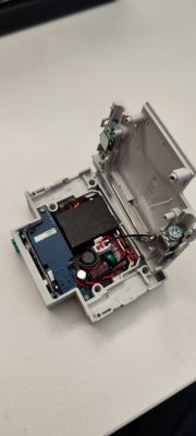
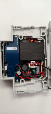
We can see here (as I assume correctly, a 60A 250V relay from "AT"[?]) and quite tightly packed integrated circuits. The whole thing consists of three PCB boards. The first one can be easily removed by unscrewing the screw in the upper right corner of the PCB (with the left side of the MCB facing us). After removing it, the whole thing looks like this:
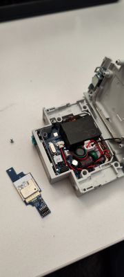
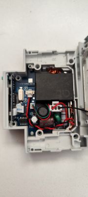
The board that comes out first is the one that interests us the most because it is responsible for WiFi connectivity. In fact, we could stop at this stage of disassembling the MCB, but since this device is not available on the forum yet, we will take a closer look inside.
The BK7231N board itself looks like this:
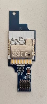
In order to upload the OpenBeken software, I had to unsolder the white board from the blue board, which actually only connects the E469716 board with the rest of the MCB. Everything after desoldering looks like this:
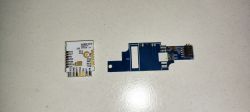
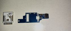
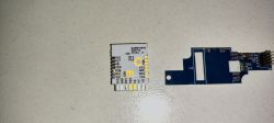
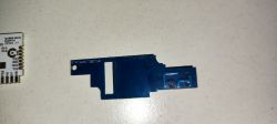
The board with the WiFi module seems to be a normal board, but after reading the software we will get the following result of the tuya config analysis:
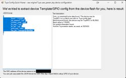
The flashing software suggests that it is probably TuyaMCU, but I do not agree with this conclusion, such a poor config is simply due to the fact that the WiFi module is only responsible for communication with WiFi and data transfer in this MCB, it does not directly control anything and he only performs (or rather delegates) the tasks entrusted to him through commands. These tasks are transferred to the HC32F460 microcontroller, which is located on the board with the display (OLED?) and controls it. The display board looks like this:
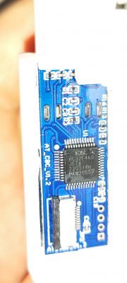
HC32F460 is apparently a clone of the more famous stm32f103c8t6 and according to the datasheet it has i2c connectors for communication with an OLED display or other peripherals (of course, there are many more protocols and I am mentioning the ones that concern us here), and a UART bus which is used to communicate with WiFi module (baudrate is probably 115200 because it is set in the WiFi module configuration, but I may be wrong and it concerns something else). The uC itself also has a built-in EEPROM memory, so there are no EEPROM chips on the other boards (probably not, as I wasn`t able to read the markings of one of the chips on the PCB - photo below).
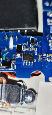
The second die that we can find on the board (HT7017?):
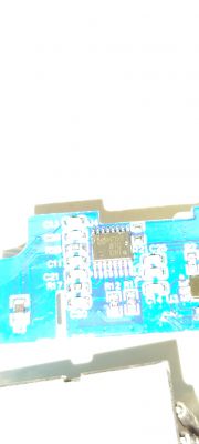
This die looks like a die measuring energy consumption.
The entire back of the PCB (the main and largest one looks like this):
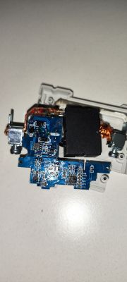
I am also sending inputs (with original software) from the BK7231N board.
When it comes to the configuration of the entire MCB, this is a problem that I have not solved yet (I assume that you need to send the appropriate TuyaMCU commands to the HC32F460, but I still don`t know how to do it exactly and therefore I would also like to ask for some technical support to create a configuration file especially for this MCB with energy consumption measurement.
NOTE: The display, fuse status memory, buttons, etc. work correctly even after uploading OpenBeken, this is due to the fact that the BK7231N does not control these peripherals, so any changes in its software do not change the operation of the counter (they only "stupid" it with the function of connecting to WiFi and sending data to the application from China). I`m not connecting the MCB itself for now until I manage to create a configuration file (I hope together ) for this device. The MCB is currently connected to the dummy load so that it can be easily accessed if necessary and that any calibration can be made based on a known load.

I looked on the forum for this fuse model, but to no avail (it`s a total novelty on the forum, so I decided to write this entry).
Let`s start from the basics, to disassemble the fuse itself, you need to "pick out" the metal pins that hold it together (there are six of them and the side we start from is not important because it is important to bend the edge of the pin inward and then gently knock out the rod), I am writing about this step because I was looking for quite a long time how to disassemble this type of MCB fuse. Once we have removed all the rods (they are gold, so they are easy to see), gently pry off the latches visible on the top of the housing. After these steps, you should now have the MCB switch open.
Now let`s move on to the most interesting stage, i.e. the interior, which looks like this:


We can see here (as I assume correctly, a 60A 250V relay from "AT"[?]) and quite tightly packed integrated circuits. The whole thing consists of three PCB boards. The first one can be easily removed by unscrewing the screw in the upper right corner of the PCB (with the left side of the MCB facing us). After removing it, the whole thing looks like this:


The board that comes out first is the one that interests us the most because it is responsible for WiFi connectivity. In fact, we could stop at this stage of disassembling the MCB, but since this device is not available on the forum yet, we will take a closer look inside.
The BK7231N board itself looks like this:

In order to upload the OpenBeken software, I had to unsolder the white board from the blue board, which actually only connects the E469716 board with the rest of the MCB. Everything after desoldering looks like this:


The board with the WiFi module seems to be a normal board, but after reading the software we will get the following result of the tuya config analysis:

The flashing software suggests that it is probably TuyaMCU, but I do not agree with this conclusion, such a poor config is simply due to the fact that the WiFi module is only responsible for communication with WiFi and data transfer in this MCB, it does not directly control anything and he only performs (or rather delegates) the tasks entrusted to him through commands. These tasks are transferred to the HC32F460 microcontroller, which is located on the board with the display (OLED?) and controls it. The display board looks like this:

HC32F460 is apparently a clone of the more famous stm32f103c8t6 and according to the datasheet it has i2c connectors for communication with an OLED display or other peripherals (of course, there are many more protocols and I am mentioning the ones that concern us here), and a UART bus which is used to communicate with WiFi module (baudrate is probably 115200 because it is set in the WiFi module configuration, but I may be wrong and it concerns something else). The uC itself also has a built-in EEPROM memory, so there are no EEPROM chips on the other boards (probably not, as I wasn`t able to read the markings of one of the chips on the PCB - photo below).

The second die that we can find on the board (HT7017?):

This die looks like a die measuring energy consumption.
The entire back of the PCB (the main and largest one looks like this):

I am also sending inputs (with original software) from the BK7231N board.
When it comes to the configuration of the entire MCB, this is a problem that I have not solved yet (I assume that you need to send the appropriate TuyaMCU commands to the HC32F460, but I still don`t know how to do it exactly and therefore I would also like to ask for some technical support to create a configuration file especially for this MCB with energy consumption measurement.
NOTE: The display, fuse status memory, buttons, etc. work correctly even after uploading OpenBeken, this is due to the fact that the BK7231N does not control these peripherals, so any changes in its software do not change the operation of the counter (they only "stupid" it with the function of connecting to WiFi and sending data to the application from China). I`m not connecting the MCB itself for now until I manage to create a configuration file (I hope together


Comments
Very interesting, fuse, current measurement and control/reading by applications in one. Thanks for sharing how to remove the fuse and how to change the software. If you give me the parcel locker, I will... [Read more]
An interesting article and kudos for using the correct phrase when talking about "energy consumption", while today everyone is trying to convince us that "we consume electricity" on every side, starting... [Read more]
Is there any documentation for this or is this just another Chinese improvement that violates safety and common sense? It hurts me when I look at the photos, but it`s probably a professional deviation... [Read more]
In my opinion, calling it a fuse is an overstatement. [Read more]
Quoting the "manufacturer", it is "Smart WiFi Switch with metering function – TO-Q-SY1-JWT" It is not a fuse and cannot perform any protective functions per se. It could supposedly be subsumed into a... [Read more]
Nie do końca wiem o co chodzi ze zdjęciami ale niektóre są prześwietlone specjalnie aby było widać dokładnie oznaczenie chip-u który się tam znajduje. Jestem zawsze otwarty na sugestie :). Jeśli chodzi... [Read more]
I see that the device will be cloud free. To run them in OpenBeken , you need to know the baud rate of TuyaMCU, and the dpID (identifiers) of the variables along with their types, because they change... [Read more]
I will add one more interesting fact... the relays in these devices are probably bistable - there is an interesting full-bridge circuit for controlling the relay in the sot23-6 housing - I have something... [Read more]
I actually encounter bistable relays in this type of equipment. IN TONGOU TO-Q-SY1-JWT and Zmai90 I saw one like that too. At OBK we wrote a driver for this Bridge . But in order not to mislead... [Read more]
https://obrazki.elektroda.pl/4025598300_1706732885_thumb.jpg This is what I received in the console after starting TuyaMCU (I completely forgot about it yesterday when I wrote the post), it looks like... [Read more]
Post all IoT devices you have, but please do not duplicate existing topics, we want to reach 500 devices soon: https://openbekeniot.github.io/webapp/devicesList.html I`m afraid to check how many of them... [Read more]
dpID 141 looks like it is simply an ID for controlling the display backlight :D , I will try to create a script that will search for dpID by force. As soon as I find out more, I will write an update. [Read more]
Please try the query command again. Does it crash every time with an error after a few IDs? Does this device allow you to change the state of the relay using a physical button? The physical operation... [Read more]
Where can this "device" be found on the Internet? Any description, photos, price? My google doesn`t know anything about it. :( [Read more]
https://a.aliexpress.com/_EyCIK5X I bought this auction on Aliexpress. Added after 58 [minutes]: I managed to determine that the relay has dpID 16, (but e.g. dpID 11 turns off the relay without... [Read more]
I haven`t seen a device with a command yet 52 (0x34). It seems that they seriously need to change something and add robots to us. I did some research and it looks like it`s: // From MCU. Response... [Read more]
I`m not sure if this would bring us closer to receiving energy consumption measurements, but if I didn`t try and think about it, I can`t force TuyaMCU to give me the dpID containing the value of energy... [Read more]
Sometimes it is simpler, sometimes more difficult, dpIDs are not standardized at Tuya. When I was developing another device with @xury, the measurements were immediately available. Are you not sending... [Read more]
As I wrote in the edit of the previous answer, I executed the command uartSendHex 55 aa 00 34 00 02 04 00 39 and the effect is that I no longer receive constant questions from the MCU and the logs... [Read more]