 .
.
Here's a short presentation of Tuya's 3-phase energy meter offering web access to measurements. I will test its application here, and then change its firmware to run it without the cloud and connect it to Home Assistant. This will require an analysis of its TuyaMCU communication protocol, which I will also describe here. It's going to be ambitious, as it's one of the more expensive products I've redesigned - you can buy it domestically for around £300, although I just received it for redesign from a reader - the aim was to upload OpenBeken .
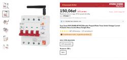
The equipment shown here goes by various names, it can be found under Fuse 3 Phase WiFi Switch 4P Tuya 63A 6KV Energy Measurement Antenna or by one of the model names: ZXB3-125/W. If imported from China, the purchase can be much cheaper than in our country:
 .
.
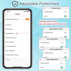
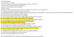
Some information from the sellers:
 .
.
 .
.
 .
.
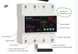
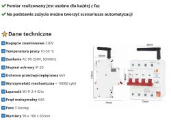
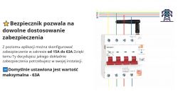
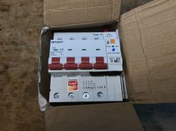
So here we have a DIN-rail device that offers both mains measurements (three phases separately) and on/off capability, as well as programmable protection/alarms. Plus an aerial and an RS485 port.
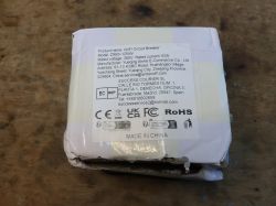
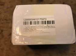
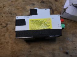
Let's take a look at the contents of the kit:
 .
.
 .
.
 .
.
 .
.
We also get an aerial, which I have not included in the photos.
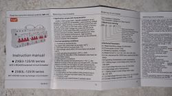
Here are clear pictures of the instructions, along with information on what this meter offers and how to connect it:
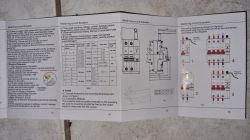
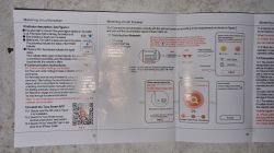
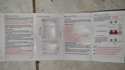 .
.
Note: Related topic .
I have already done a similar redesign for another device - there too, it was a TuyaMCU-based system. Feel free to check out the related series:
Energy meter/thermostat with LCD - S1TW-FR - first impression, Tuya application .
Advanced energy meter/thermostat with LCD Atorch S1TW-FR - cloudless operation
Application capabilities .
The RESET button on the housing is used for pairing. Proceed as with other Tuya devices:
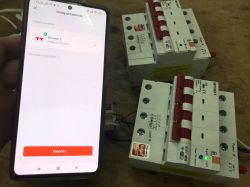 .
.
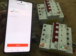
Immediately afterwards we can control and read the measurements. Here is a short video presentation:
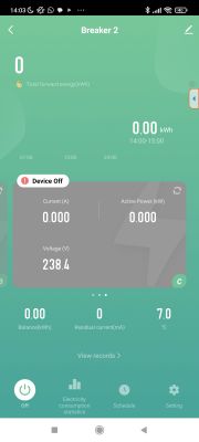
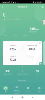
Once paired with Tuya, we get first of all access to the measurements of each phase (voltage, current, power), the possibility to switch on or off all phases together, and additional information such as the total electricity measurement, the last hour's electricity measurement or there sensor temperature.
 .
.
 .
.
Measurement history (graphs) is also available, but I personally miss counting the energy separately for each phase.
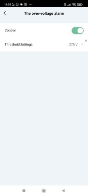
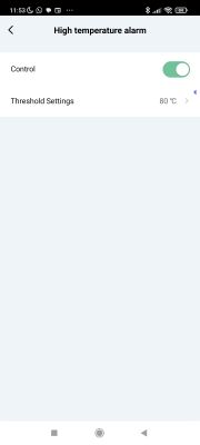
In addition, we have the possibility to set "alarms" with appropriate triggers, too high voltage, too high electricity, etc:
 .
.
 .
.
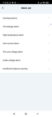 .
.
Tuya also allows the creation of scenarios based on the state of this product, as it does with other devices.
Interior of the product .
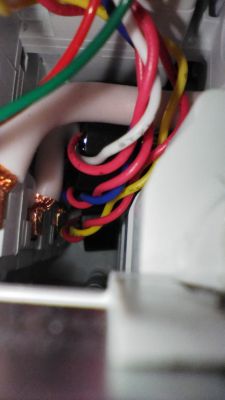
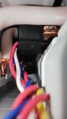
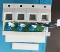
Unfortunately, here the device is slightly better secured than usual. In addition to removing the three screws, we also have to ream the rivet ends here. In the case of the meter from the topic this has already been done by a reader, below are the photos:
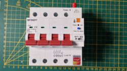
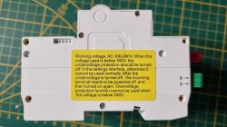
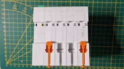
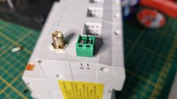
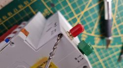

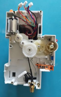
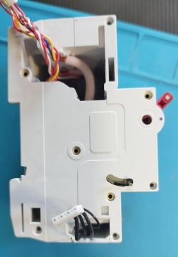
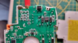
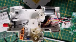
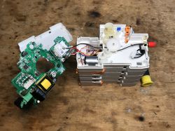
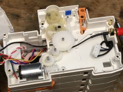
This is how we get inside:
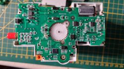
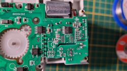
 .
.
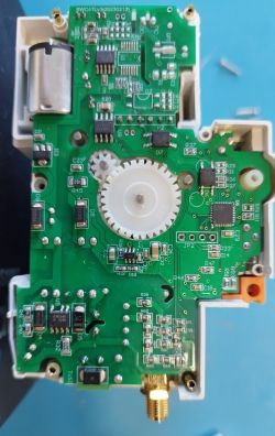
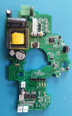
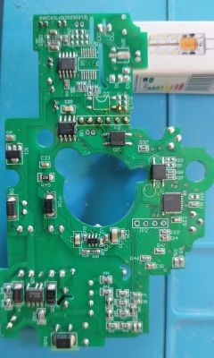
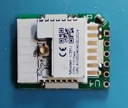
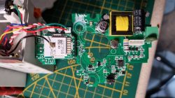
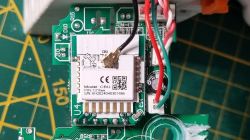
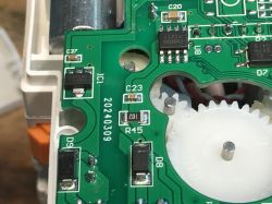
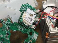
The whole is based on the RSF100BEA MCU (to handle measurements) and the CBU, the BK7231N.
 .
.
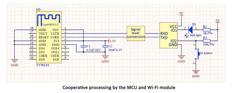
The CBU communicates with the main microcontroller via the UART, via the TuyaMCU protocol:
TuyaMCU protocol - communication between microcontroller and WiFi module .
 .
.
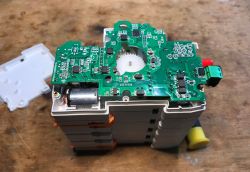
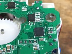
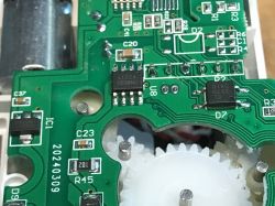
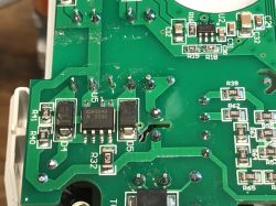
A few more pics from me:
 .
.
 .
.
 .
.
 .
.
 .
.
 .
.
 .
.
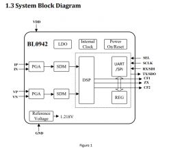
Separately for each phase here we have BL0942, each connected to the aforementioned MCU.
 .
.
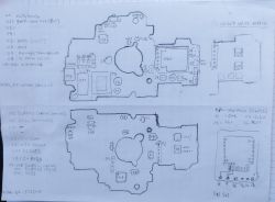
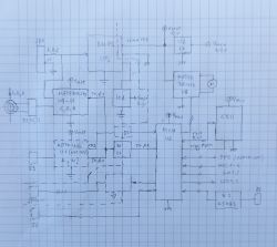
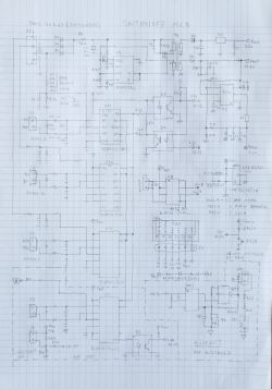
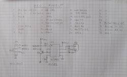
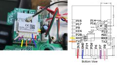
A breakdown of the board's connections to the MCU - in addition to the UART, we have two more signals here, namely a reset button and an LED indicating WiFi status. Moreover, the WiFi status issued by the BK7231N is also read by the MCU, keep this in mind when changing the Beken firmware....
 .
.
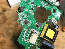
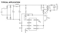
The power supply itself is provided by the ICW2540, which seems to be the controller of the small flyback converter, but I wouldn't count on there being galvanic isolation from the grid side here anyway because the BL0942 has to do the measurement somehow too:
 .
.
The role of the CN8033 I have not been able to determine.
Captured communication TuyaMCU .
Intercepting the communication between the MCU and the WiFi module can help us determine the meaning of each dpID. The whole thing has to be done with a lot of care, because the electronics of the meter are not isolated from the network, so if we connect to it with an ordinary USB to UART converter we can make a short circuit and damage both the meter and the computer. For this reason I have used ADuM1200/ADuM1201 based isolators.
The device shown here uses the slower TuyaMCU mode, which is baud 9600. The faster baud (115200) known from some similar products is not used here.
The communication can be analysed in our analyser TuyaMCU .
The capture method was twofold. For the user settings I covered the method:
1. I start the capture
2. change a setting
3. stop the capture
whereas for measurements I simply wrote down what is shown in the Tuya app and then tried to find the reported data in the packets.
The conclusions are as follows:
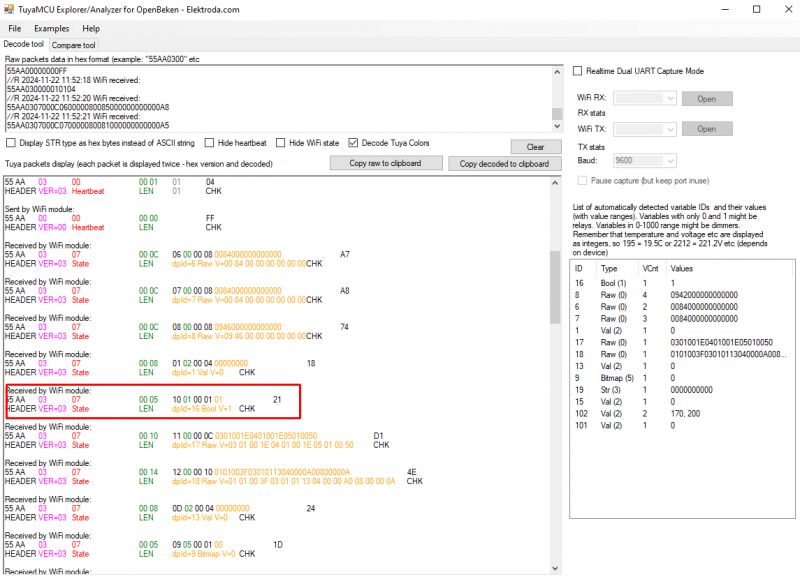
- dpID 16 is boolean, "relay" control, on or off
 .
.
- dpID 6, 7 and 8 are raw type containing current, voltage and power measurements for each phase separately, as adopted in OpenBeken RAW_TAC2121C_VCP, quoting code C:
Code: C / C++
- dpID 11 is the temperature with one decimal place, but sent as an integer, so in OBK this is the so-called Temperature_div10 type
- dpID 12 is the total electricity consumption in tens of Wh (123 corresponds to 1.23kWh)
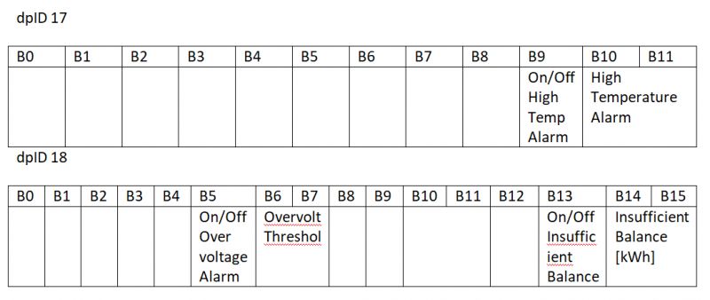
- dpID 17 and dpID 18 are longer packets, 12 bytes and 16 bytes respectively, containing the alarms (one byte as on/off and two bytes as limit for each alarm). A preliminary sketch of the meaning of the bytes:
 .
.
When the user changes the alarm setting, the entire packet with the given dpID is sent, and the MCU confirms the change by sending back the new value of the previously changed data.
In addition, I also helped myself with the method getting the dpID from the cloud through it I learned other, slightly less important dpIDs:
Code: JSON
In a similar way, I obtained ranges of values for some variables:
switch_prepayment	Boolean	"{true,false}"
clear_energy	Boolean	"{true,false}"
charge_energy	Integer
				{
				  "unit": "kW·h",
				  "min": 0,
				  "max": 999999,
				  "scale": 2,
				  "step": 1
				}
switch	Boolean	"{true,false}"
alarm_set_1	Raw	{}
alarm_set_2	Raw	{}
leakagecurr_test	Boolean	"{true,false}"


Code	Type	Values
total_forward_energy	Integer
{
  "unit": "kW·h",
  "min": 0,
  "max": 99999999,
  "scale": 2,
  "step": 1
}
phase_a	Raw	{}
phase_b	Raw	{}
phase_c	Raw	{}
fault	Bitmap	{
  "label": [
    "short_circuit_alarm",
    "surge_alarm",
    "overload_alarm",
    "leakagecurr_alarm",
    "temp_dif_fault",
    "fire_alarm",
    "high_power_alarm",
    "self_test_alarm",
    "ov_cr",
    "unbalance_alarm",
    "ov_vol",
    "undervoltage_alarm",
    "miss_phase_alarm",
    "outage_alarm",
    "magnetism_alarm",
    "credit_alarm",
    "no_balance_alarm"
  ]
}
switch_prepayment	Boolean	"{true,false}"
energy_reset	Enum	{
  "range": [
    "empty"
  ]
}
balance_energy	Integer	{
  "unit": "kW·h",
  "min": 0,
  "max": 99999999,
  "scale": 2,
  "step": 1
}
charge_energy	Integer	{
  "unit": "kW·h",
  "min": 0,
  "max": 999999,
  "scale": 2,
  "step": 1
}
leakage_current	Integer	{
  "unit": "mA",
  "min": 0,
  "max": 1000,
  "scale": 0,
  "step": 1
}
switch	Boolean	"{true,false}"
alarm_set_1	Raw	{}
alarm_set_2	Raw	{}
breaker_number	String	{
  "maxlen": 255
}
leakagecurr_test	Boolean	"{true,false}"
temp_current	Integer	{
  "unit": "℃",
  "min": -400,
  "max": 2000,
  "scale": 1,
  "step": 1
}
The only pity is that this method did not show the meaning of the alarm bytes anyway - i.e. alarm_set_1 and alarm_set_2 sets. You will have to analyse manually.
Firmware change .
According to our TuyaMCU guide:
TuyaMCU flashing, installation and configuration guide - configure dpID for Home Assistant .
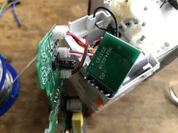
The port to change the BK7231 firmware is the same port that TuyaMCU uses, for this reason I had to solder the WiFi module board. A bit of flux and lead binder was enough:
 .
.
By the way, you can see what's under this board - the aforementioned BL0942 for measurements:
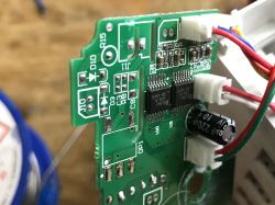 .
.
CBU I program with our flasher: https://github.com/openshwprojects/BK7231GUIFlashTool
Youtube footage can be used: https://www.youtube.com/@elektrodacom
Once programmed, the CBU needs to go back in place:
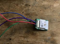 .
.
Before soldering the board in place, the holes must be cleaned of old binder:
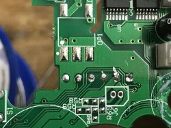 .
.
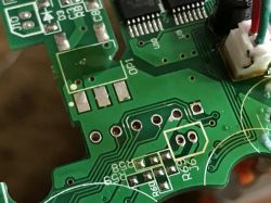 .
.
I only switch the device on again after carefully checking that the CBU has been soldered well, without any short circuits or cold solders.
ADVERTISEMENT
Startup OpenBeken .
The initial setup is the same as in Tasmota - we configure our WiFi via an open access point, and then connect to the device already via our router.
The problems start one step further down the line.
You need to configure the TuyaMCU, and although we already have templates ready for similar devices, here the hardware didn't want to report most of the dpID to me. Only basic information was sent.
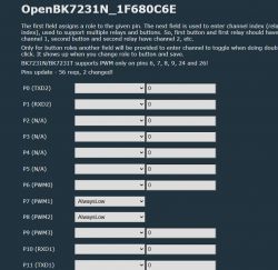
I tried the methods known from the documentation , That is, tuyamcu_sendQueryState and tuyamcu_defWifiState , but ultimately the solution was elsewhere. In the case of this device, the WiFi module should expose the appropriate logic state to one of the pins outside the UART to only allow the MCU to report additional data. For details see: How to get the TuyaMCU device to send more data? Why are the dpIDs not being sent? .
In this particular case I had to set P8 to always low mode:
 .
.
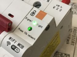
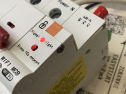
Manipulating P8 not only changes the state of the LED on the case, but also determines how much data the MCU can send. The MCU only sends full data when the state on P8 is low, i.e. the green LED is on:
 .
.
 .
.
Only after this change was I able to move on, but then I encountered another problem....
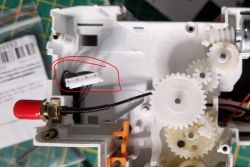
Only one phase was working - or more accurately for the others the measurements were zero. After a longer investigation, the culprit of the problems turned out to be a plug inserted the other way round:
 .
.
In theory, it should not be possible to insert it the other way round, but as you can see, it is possible, especially as the wires are very short and generally the whole thing is very difficult to assemble once opened, and the plug from the photo has to be inserted with tweezers....
Eventually, however, the following script was worked out:
startDriver TuyaMCU
startDriver NTP
//tuyaMcu_setBaudRate 115200
// not really needed here
tuyaMcu_defWiFiState 4

setChannelType 1 Toggle
linkTuyaMCUOutputToChannel 16 bool 1


// phase A
setChannelType 2 Voltage_div10
setChannelType 3 Current_div1000
setChannelType 4 Power
linkTuyaMCUOutputToChannel 6 RAW_TAC2121C_VCP 2 3 4

// phase B
setChannelType 5 Voltage_div10
setChannelType 6 Current_div1000
setChannelType 7 Power
linkTuyaMCUOutputToChannel 7 RAW_TAC2121C_VCP 5 6 7

// phase C
setChannelType 8 Voltage_div10
setChannelType 9 Current_div1000
setChannelType 10 Power
linkTuyaMCUOutputToChannel 8 RAW_TAC2121C_VCP 8 9 10

// temperature
setChannelType 11 Temperature_div10
linkTuyaMCUOutputToChannel 102 val 11

// balance (increases)
linkTuyaMCUOutputToChannel 1 val 12
setChannelType 12 EnergyTotal_kWh_div100
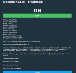
Everything according to our documentation , only it is worth mentioning that the dpID type RAW_TAC2121C_VCP takes the index of the first channel (voltage) as an argument and further assumes by default that the next channel is current and the next one is power. Just as the name suggests, Voltage, Current, Power.
Panel view:
 .
.
Now you can freely name the channels you have set up and do Home Assistant Discovery to connect the device to the HA.
Summary .
This is probably one of the most expensive Tuya devices I have processed and it was not without its problems. At first everything went as expected, from the outset I expected it to be based on the TuyaMCU mechanism so I followed the trodden path already followed but then new problems arose. The first problem was that here the TuyaMCU doesn't report the status of the "connection to the cloud" via the UART, but only via a separate pin, and figuring this out it took me a bit of time , and the second problem was this reverse-inserted plug - it was because of it that the second and third phases stubbornly didn't show measurements....
In the end, however, the base is now working.
The converted device works 100% locally, independently of the manufacturer's servers and can be easily connected to the Home Assistant , as well as freely programmed and scripted.
Now the following remains to be done two things:
- activation of advanced functions (overcurrent protection) which are sewn into those specialised raw type packets with dpID 17 and 18; this will require their proper parsing and also their sending (so that the user can change the settings). Ready-made mechanisms are not sufficient for this, because ready-made mechanisms assume that a given dpID is a single variable of the type, e.g. integer or boolean, while here a single dpID is a sequence of bytes (a set of many alarms).
- testing and developing the connection via RS485 offered by this series - maybe someone reading has tried it? At this point I don't even know if this is functional on this model....
I would like to complete this soon - maybe there will be a second topic in the series? .
I've got some more in the queue:
While I'm at it, I'll ask if anyone has used this type of meter before, or maybe even converted it so that it works with HA? .
I am attaching the captured TuyaMCU packet from the factory software of this device. .
Cool? Ranking DIY Helpful post? Buy me a coffee.


