Teardown & Flashing Guide for Ener-J Tuya Touch Switch Models ETS301W & ETS302W
This covers the teardown and flashing method for both the following models (both physically stripped and flashed).
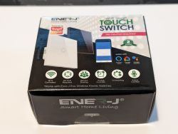
1 Gang White - Model No. ETS301W - SKU SHA5312 - Batch No. S627
2 Gang White - Model No. ETS302W - SKU SHA5313 - Batch No. S627
Both of the above models state they do not need a dedicate neutral at the switch, they provide a capacitor to be installed at the light across neutral and the live from L1 on the switch. They do not provide a neutral terminal to use, if you do have a neutral at the switch like many newbuild houses, later in the post I provide details of a simple mod to add a neutral tail to avoid needing the capacitor and using the neutral at the switch.
Unboxing the switch & what is in the box.
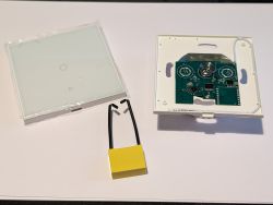
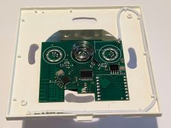
Initial inspection was a little worrying as the typical daughter board such as the CBU was missing and the whole unit appears to be integrated on one board, you can see the WIFI antenna and the frequency crystal on the lefthand side of the board which is also where the BK7231N is located.
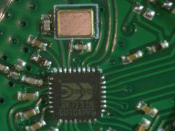
A close-up identifies the BK7231N.
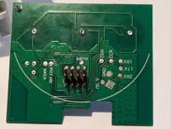
Seeing this I thought it was going to be a nightmare to trace and find solder pads, but to my relief and thanks to the developers, the switch pcb just pulls off from a 8 pin socket and on the reverse side reveals labelled solder pads, which are large enough to solder directly to and for my first switch as I was eager to make progress I did solder successfully to these.
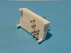
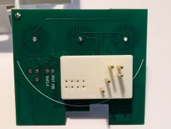
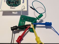
I, like many of you, prefer simpler solderless flashing solutions, so I set to with CAD and came up with a handsfree clip on pogo pin adapter, this uses the 8 pin connector on the PCB to securely and accurately locate the adapter and I prefer to use clip on test wires to make the connection, but you could equally solder jumper cables to the pogo pins. The adapter has been made readily available here at www.printables.com and is of course free to download and print yourself (If you don't have a 3D printer and want one printed with pogo pins installed please pm me). In the last picture with my test wires clipped in place, Red(3.3V), Black(GND), Yellow(Tx), Blue(Rx) and Green(CEN) this device responded well to the tapping of CEN to GND to start the flashing process.
Template for the 1 Gang Model No. ETS301W
Template for the 2 Gang Model No. ETS302W
For those of you who have read this far and want the additional mod to utilize a neutral at the switch, this is less than a 5 minute process, you will need the correct colour and guage multi strand cable for your country, a small phillips screwdriver and a soldering iron.
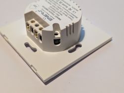
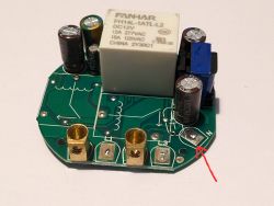
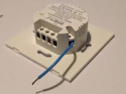
Whilst the neutral terminal is not provided in these models, the solder pad is accessible and the casing has the same profile providing space for a tail to be passed through.
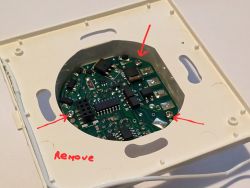
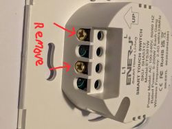
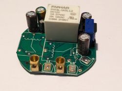
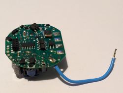
First remove the switch pcb to reveal the high voltage relay board, then remove the 3 small screws per photo, then remove all the terminal screws per photo. Remove the pcb and identify the neutral solder pad, solder on your neutral tail and re-assemble.

1 Gang White - Model No. ETS301W - SKU SHA5312 - Batch No. S627
2 Gang White - Model No. ETS302W - SKU SHA5313 - Batch No. S627
Both of the above models state they do not need a dedicate neutral at the switch, they provide a capacitor to be installed at the light across neutral and the live from L1 on the switch. They do not provide a neutral terminal to use, if you do have a neutral at the switch like many newbuild houses, later in the post I provide details of a simple mod to add a neutral tail to avoid needing the capacitor and using the neutral at the switch.
Unboxing the switch & what is in the box.

Initial inspection was a little worrying as the typical daughter board such as the CBU was missing and the whole unit appears to be integrated on one board, you can see the WIFI antenna and the frequency crystal on the lefthand side of the board which is also where the BK7231N is located.

A close-up identifies the BK7231N.

Seeing this I thought it was going to be a nightmare to trace and find solder pads, but to my relief and thanks to the developers, the switch pcb just pulls off from a 8 pin socket and on the reverse side reveals labelled solder pads, which are large enough to solder directly to and for my first switch as I was eager to make progress I did solder successfully to these.

I, like many of you, prefer simpler solderless flashing solutions, so I set to with CAD and came up with a handsfree clip on pogo pin adapter, this uses the 8 pin connector on the PCB to securely and accurately locate the adapter and I prefer to use clip on test wires to make the connection, but you could equally solder jumper cables to the pogo pins. The adapter has been made readily available here at www.printables.com and is of course free to download and print yourself (If you don't have a 3D printer and want one printed with pogo pins installed please pm me). In the last picture with my test wires clipped in place, Red(3.3V), Black(GND), Yellow(Tx), Blue(Rx) and Green(CEN) this device responded well to the tapping of CEN to GND to start the flashing process.


Template for the 1 Gang Model No. ETS301W
Code: JSON
Template for the 2 Gang Model No. ETS302W
Code: JSON
For those of you who have read this far and want the additional mod to utilize a neutral at the switch, this is less than a 5 minute process, you will need the correct colour and guage multi strand cable for your country, a small phillips screwdriver and a soldering iron.
Whilst the neutral terminal is not provided in these models, the solder pad is accessible and the casing has the same profile providing space for a tail to be passed through.
First remove the switch pcb to reveal the high voltage relay board, then remove the 3 small screws per photo, then remove all the terminal screws per photo. Remove the pcb and identify the neutral solder pad, solder on your neutral tail and re-assemble.


Comments
This is a very strange PCB track routing, I haven't seen anything like that before: Thank you for sharing the templates. Added after 8 [hours] 54 [minutes]: EDIT: Devices added, they should be... [Read more]