DIY Clock/calendar/thermometer/hygrometer/IR receiver BK7231T MAX7219 DHT11
 .
.
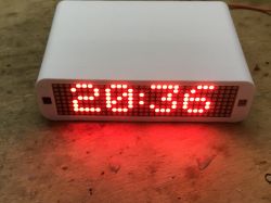
Hello, I'm going to present here a little DIY project that I did over the weekend. My project is based on a WB2S WiFi module (BK7231T), a MAX7219 matrix LED display, a DHT11 thermometer/hygrometer, an IR receiver, a photoresistor and a housing from a 3D printer. The gadget described here is fully compatible with Home Assistant, and runs OpenBeken , which allows it to continuously, for example, report measurements to HA and also forward received IR codes to HA. In addition to this, the firmware is also capable of handling these codes independently (without HA) and e.g. forwarding commands via HTTP GET requests to OpenBeken or Tasmota devices, which makes it possible, for example, to script the IR remote control to control other smart devices at home without the need for any main server/Home Assistant.
Introduction .
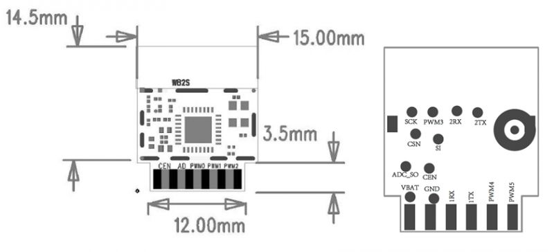
At the heart of the project is the WB2S module (BK7231T):
 .
.
Outputs (from Tuya documentation):
[/tr] Function [td:16dd78e118] Common GPIO, which is connected to the P26 pin on the internal IC
| Symbol | I/O type | Function | 1 | VBAT | P | Power supply pin (3.3 V), which is connected to the VBAT pin on the internal IC |
| 2 | PWM2 | I/O | Common GPIO, which is connected to the P8 pin on the internal IC |
| <span>3 | GND | P | Power supply reference ground pin |
| 4 | PWM1 | I/O | Common GPIO, which is connected to the P7 pin on the internal IC |
| 5 | 1RX | I/O | UART1_RXD, which is used as a user-side serial interface pin and is connected to the P10 pin on the internal IC |
| 6 | PWM0 | I/O | Common GPIO, which is connected to the P6 pin on the internal IC |
| 7 | 1TX | I/O | UART1_TXD, which is used as a user-side serial interface pin and is connected to the P11 pin on the internal IC |
| 8 | AD | AI | ADC pin, which is connected to the P23 pin on the internal IC |
| 9 | PWM4 | I/O | Common GPIO, which is connected to the P24 pin on the internal IC |
| 10 | Price | I | Low-level reset, high-level active (internally pulled high) Docking IC-CEN |
| 11 | PWM5 | I/O |
I chose the module because I already had several of these (received from a user who replaced them with ESPs in smart devices) and because I need platforms to test my firmware:
https://github.com/openshwprojects/OpenBK7231T_App
I wanted to have some kind of platform to test new peripherals, for this reason I gathered what I had of the parts into one project and this is how this clock was created.
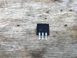
Apart from the peripherals there is basically only a 3.3V LDO regulator on board, here a MIC29150 3.3WU, although a regular AMS1117-3.3V would also fit.
Uploading the batch .
To upload the OBK I used:
https://github.com/openshwprojects/BK7231GUIFlashTool
All according to the instructions from the link, but you can also look at the flashing tutorials on Youtube Elektroda.com:
https://www.youtube.com/@elektrodacom
Prototype
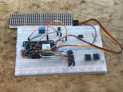
I made a prototype still on the WB3S soldered into the base of the NodeMCU:
 .
.
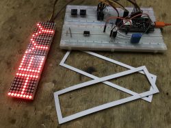
Everything is connected via OBK drivers, which are configurable and can be scripted with the OBK scripting language without recompiling the batch.
 .
.
Build, board
I decided to print the case on a 3D printer, my Ender 3 Pro, from PLA filament. I made the board guerrilla-style, from a prototype/drilled board. Let's start with the board. Here is the WB2S still with the wires from the contact board:
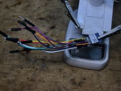 .
.
I then desoldered these cables and soldered the legs to it:
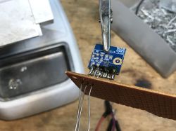
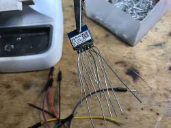 .
.
Everything went nicely into the plate:
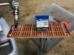 .
.
These boards are comfortable to solder, just make sure the temperature is low, otherwise the solder fields fall off:
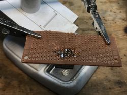 .
.
My LDO regulator, fairly unknown, MIC29150 3.3WU, and it's in SMD housing, but I managed:
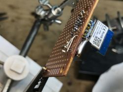
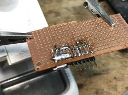 .
.
A continuation of, as some call it, "sculpting". GPIO pinouts:
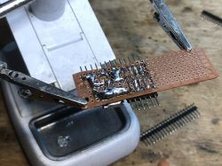
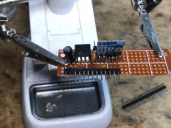 .
.
A GPIO map was also created during the work - otherwise it will be easy to get lost when servicing the design in the future:
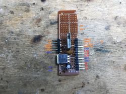 .
.
The additional pads, located on the 'back' of the WB2S, I have also taken the liberty to derive. The UART2 port could come in handy, if only as a simple GPIO:
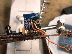
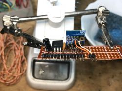 .
.
Then work on the enclosure began. I started by sizing up the display:
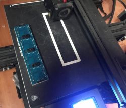 .
.
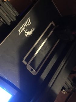 .
.
The project was created in Blender, the enclosure will be a two-part...
Test fitting for the case, the display part of the case is not complete here:
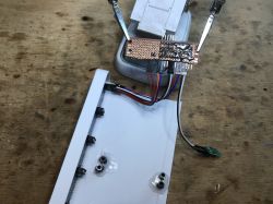 .
.
In an ideal world, you wouldn't need to glue plastic spacers onto the case, you just include them in the 3D design, but this is just a prototype. Maybe in the next version I'll make a dedicated PCB for it.
Again, a fitting:
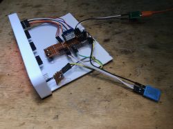
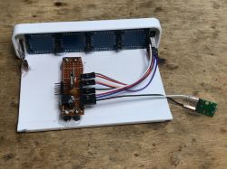
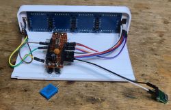
 .
.
First tests:
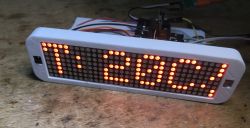
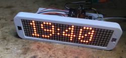
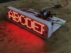 .
.
Almost complete case set, only without the rear panel. One part slides into the other. The display sticks to the base and the top slides over it.
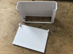 .
.
OpenBeken configuration .
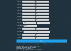
My firmware is designed to do a lot without programming, so configuring the device comes down to selecting pin roles:
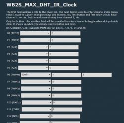
 .
.
On P6 is the DHT11, its associated channels are 1 (for temperature) and 2 (for humidity).
On P23 is the ADC (photoresistor, actually a photoresistor and a simple resistor forming a voltage divider), the associated channel is channel 0. This photoresistor will be used to adjust the brightness of the display depending on the external lighting.
There is an IR receiver on P24.
The measurement results can be seen on the main web panel of the device:
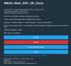 .
.
In addition, the device is scripted in autoexec.bat. The script enables the MAX72XX driver, starts the NTP, also starts the clock driver, and allows control of other devices via the IR remote - mediated by GET requests (SendGet command):
startDriver MAX72XX
MAX72XX_Setup 0 1 26
startDriver NTP
startDriver MAX72XX_Clock
ntp_timeZoneOfs 2
The following snippet creates aliases for commands that control other devices:
alias my_ledStrip_off SendGet http://192.168.0.200/cm?cmnd=POWER%20OFF
alias my_ledStrip_plus SendGet http://192.168.0.200/cm?cmnd=backlog%20POWER%20ON;add_dimmer%2010
alias my_ledStrip_minus SendGet http://192.168.0.200/cm?cmnd=backlog%20POWER%20ON;add_dimmer%20-10
alias main_switch_off SendGet http://192.168.0.159/cm?cmnd=POWER%20OFF
alias main_switch_on SendGet http://192.168.0.159/cm?cmnd=POWER%20ON

alias my_send_style_cold SendGet http://192.168.0.210/cm?cmnd=backlog%20CT%20153;%20POWER%20ON
alias my_send_style_warm SendGet http://192.168.0.210/cm?cmnd=backlog%20CT%20500%20POWER%20ON
alias my_send_style_red SendGet http://192.168.0.210/cm?cmnd=backlog%20color%20FF0000%20POWER%20ON
alias my_send_style_green SendGet http://192.168.0.210/cm?cmnd=backlog%20color%2000FF00%20POWER%20ON
alias my_send_style_blue SendGet http://192.168.0.210/cm?cmnd=backlog%20color%200000FF%20POWER%20ON
alias my_send_style_plus SendGet http://192.168.0.210/cm?cmnd=backlog%20POWER%20ON;add_dimmer%2010
alias my_send_style_minus SendGet http://192.168.0.210/cm?cmnd=backlog%20POWER%20ON;add_dimmer%20-10
The following snippet maps IR events to the created aliases/commands:
// 1
addEventHandler2 IR_Samsung 0x707 0x4 my_ledStrip_off
// 2
addEventHandler2 IR_Samsung 0x707 0x5 my_ledStrip_plus
// 3
addEventHandler2 IR_Samsung 0x707 0x6 my_ledStrip_minus
// 4
addEventHandler2 IR_Samsung 0x707 0x8 main_switch_off
// 5
addEventHandler2 IR_Samsung 0x707 0x9 main_switch_on
// 6
addEventHandler2 IR_Samsung 0x707 0xA startScript autoexec.bat next_light_style
// 7
addEventHandler2 IR_Samsung 0x707 0xC my_send_style_plus
// 8
addEventHandler2 IR_Samsung 0x707 0xD my_send_style_minus

// stop autoexec execution here
return
The following snippet is a lighting style switch:
// this is function for scrolling light styles
next_light_style:

// add to ch 10, wrap within range [0,5]
addChannel 10 1 0 5 1

// start main switch
//main_switch_on

if $CH10==0 then my_send_style_cold
if $CH10==1 then my_send_style_warm
if $CH10==2 then my_send_style_red
if $CH10==3 then my_send_style_green
if $CH10==4 then my_send_style_blue
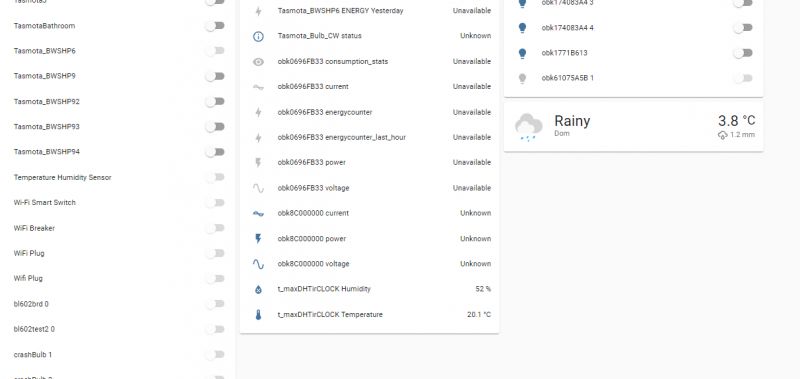
Home Assistant Discovery correctly pairs this device with HA, without having to write a single line of Yaml code:
 .
.
Gallery
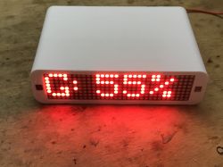
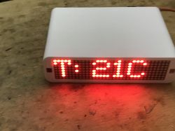
A few pics of the final operation of the device:

 .
.
It alternates between showing the current time from the internet and the measurements from the DHT11.
Now I see a small typo, but maybe no one will realise .... it does not affect the operation.
Summary .
This is just a prototype, but I think it is fully functional and does the job well. I didn't do the board under it, but the pinout of my "sculpture" is fully sufficient for servicing, as well as the enclosure in its current form passes the test. In a free moment, it would be possible to make an "official version", already with the board designed under it and with the PCB mounts already included in the 3D printout. I will have to think about it, maybe I will design something in Eagle and order 5/10 pieces in China in the cheapest price range (10cm by 10cm), or I will etch something myself, but about that another time. The main thing is that the front rather looks good and gives a nice effect both day and night.
It's also worth noting here that the whole gadget allows me to use the remote to control any number of devices in the room without Home Assistant. The project receives the IR signal and then makes a GET request to the OBK or Tasmota device in question. HA here is not needed, although if I want to use it, I can simply forward it on to MQTT when an IR event is received.... the possibilities are very high.[/td]


Comments
Super project. [Read more]
Thanks, then I'll add a handful more loose information. The project compiles on the following platforms: https://obrazki.elektroda.pl/3711576500_1725007421_bigthumb.jpg . But the IR may be missing... [Read more]
Nice end result, I wonder if hiding the display behind the milky plexiglass would have the effect of smoothing out the displayed characters. [Read more]