logo elektroda
logo elektroda
X
logo elektroda

WiFi thermometer with SHT30 - description of uploading OpenBK, integration with Home Assistant and p

@GUTEK@ 5109 18
ADVERTISEMENT
Treść została przetłumaczona polish » english Zobacz oryginalną wersję tematu
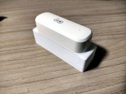
  • WiFi thermometer on a 3D-printed base
    Applies to the model described here: https://www.elektroda.pl/rtvforum/topic3945688.html

    Hello, in this description I will present my method of connecting WiFi thermometers with the SHT30 sensor, popular on AliExpress, to Home Assistant and changing the power supply to an 18650 battery. The main reason for changing the power supply is the power consumption of WiFi and the very inefficient original source, which are AAA batteries. Additionally, to nicely hide the battery, I designed and 3D printed an additional housing for the basket with the cell, attached to the latches in the thermometer.

    A little note here. The thermometers use the BK7231N system for which the maximum voltage is 3.6V. However, the voltage of a fully charged cell is 4.2V. My thermometers powered this way work properly, but I warn people who want to do what I do that it may end up damaging the system.

    1. Firmware change
    We have to start by reprogramming the system. Originally, these thermometers work with the Tuya ecosystem and cannot be connected to Home Assistant even by removing the Local Key.
    You need to upload the OpenBK firmware. There are two ways to do this. The first one is to simply open the housing and solder it to the system. Which is quite simple in this case, because the housing is assembled only with latches and fastened with one screw. There are also many descriptions on the Internet on how to program it.
    The second method is to use the Tuya Cloudcutter script, which forces the device to be in the original firmware update mode by providing the OpenBK firmware file. Since I had previously reprogrammed sockets, which were glued and opening them without destroying the casing was almost impossible, this method was the most reasonable. And now that I know it, I will also describe it for these thermometers.

    Cloudcutter is best run on a clean Linux system, you can also use a RaspberryPi 3 or newer computer. The author recommends Ubuntu, I used Debian. Additionally, a WiFi card is required because the script creates a HotSpot during operation to which the programmed device connects. You can use the built-in card if you use e.g. a laptop or a USB card. And here`s a small note: not every card will work. Initially, I tried cards based on the Realtek chipset. However, on them the script screamed that it was unable to handle HotSpot mode. Finally I used an Atheros based card, this one worked fine.
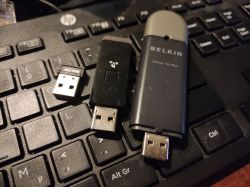
    Various-sized USB WiFi adapters on a keyboard.

    So, having a clean system with a WiFi card installed, we install Docker, which Cloudcutter requires to work.
    It`s very well described step by step on the Docker website, so I`ll just post the link:
    https://docs.docker.com/engine/install/debian/


    After correctly installing Docker, we install subsequent packages. For handling Git repositories and WiFi management. To do this, launch the console and enter:
    sudo apt install git network-manager
    Installation of git packages in a Linux terminal

    In the next step, we clone the Cloudcutter repository from Github:
    git clone https://github.com/tuya-cloudcutter/tuya-cloudcutter


    After cloning, we enter the directory ./tuya-cloudcutter/custom-firmware and there we download the OpenBK firmware in the appropriate version needed to reprogram the thermometer.
    To do this, go to the website:
    https://github.com/openshwprojects/OpenBK7231T_App/releases

    Our thermometer is on a chip BK7231N . Therefore, we must choose the firmware for this system and the version that works with Cloudcutter, i.e. described as CCtr Flash .
    We download with the wget command:
    (this is an example link, with the current fw version at the time of writing, I recommend replacing it with the current version)
    wget https://github.com/openshwprojects/OpenBK7231T_App/releases/download/1.17.379/OpenBK7231N_UG_1.17.379.bin
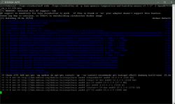
    Linux terminal window with firmware download process.

    Once we have everything downloaded, we go back to the directory above and run the tuya-cloudcutter.sh script with the appropriate parameters. The first launch may take quite a long time as additional elements needed for operation are downloaded and Docker containers are created.
    So we run the script with variables, where -p is the profile of our device. The current list of supported devices can be found here:
    https://github.com/tuya-cloudcutter/tuya-cloudcutter.github.io/tree/master/devices

    The -f variable is the name of the firmware file that we downloaded earlier. So the full syntax:
    sudo ./tuya-cloudcutter.sh -p tuya-generic-temperature-and-humidity-sensor-v1.1.17 -f OpenBK7231N_UG_1.17.379.bin

    At the very beginning, the script will display important information, "WARNING: Selected wifi AP support: yes" if it does not say "yes" or "yes" at the end, stop the operation by pressing Ctrl+C because the WiFi card does not support HotSpot mode and the script will not work properly. If we continue, the necessary elements will be downloaded first:
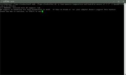
    Terminal window displaying WiFi support information. Terminal window with Tuya Cloudcutter script running on Debian.

    At this point, all instructions will be described on the screen. We insert the batteries into the thermometer and we need to put it in the slow blinking mode (HotSpot mode). To do this, hold down the RESET button. First, the LED will start flashing quickly and this is not this mode yet. We press the button again and hold it for a while, only then will the LED start blinking slowly and the script will immediately detect the thermometer and start working.
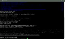
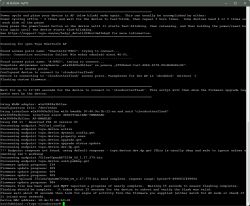
    Screenshot from PuTTY console showing the process of changing the firmware of a Tuya thermometer using Cloudcutter.

    At this point, the script will make a copy of the device configuration, and the thermometer itself will reset and the LED will turn off. We have to repeat the procedure of pressing RESET again until it flashes slowly. Now the script will start working properly. The thermometer will be detected again and the OpenBK firmware upload will start.
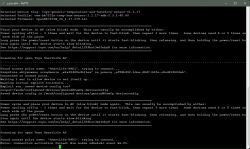
    Screenshot of PuTTY with WiFi thermometer configuration logs. Terminal with firmware update instructions

    2. Configuration and connection to Home Assistant
    If everything above went correctly, we already have OpenBK loaded. And the thermometer itself works in HotSpot mode, which you need to connect to to start configuration.
    This can be done using a smartphone, tablet or laptop. The network will start with a name OpenBK… and it will be unsecured.
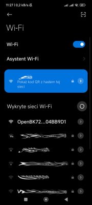
    List of detected Wi-Fi networks on a smartphone screen with the OpenBK72 network highlighted.

    The next step after connecting is to launch a web browser and enter the address
    http://192.168.4.1
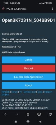
    OpenBK7231N configuration interface screen with device control buttons.

    We can now start the configuration, I suggest first connecting to our WiFi network. To do this, we enter "Config" "Configure WiFi & Web" . In the fields below "Use this to connect to your WiFi" enter the name of our network - SSID and the key – Password and confirm with the button Submit at the bottom of the page.
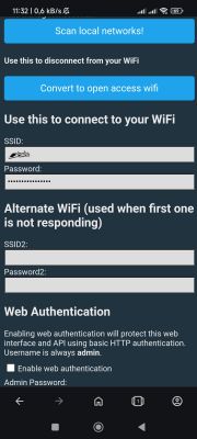
    Screenshot of a mobile app for WiFi configuration.

    The device will restart and connect to our WiFi. By default, it is configured to receive an IP address from a DHCP server. Therefore, we need to check what address it received, e.g. in the router logs. Once it is known, enter it in the browser again and the same page as before will be displayed. The most convenient way to do this is from your computer`s browser.
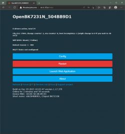
    OpenBK7231N configuration screen

    Now you need to assign the pin configuration so that the firmware knows which pin of the Beken chip is connected to. This can be done manually, but a ready-made configuration is available for this thermometer.
    That`s why we click on "Launch Web Application" , on the page that opens in a column "Devices:" we choose ours "Chipset" That is BK7231N , and in the list below "Tuya Generic Temperature and Humidity Sensor Battery Powered SHT30" . A photo of the board will be displayed and the pin configuration will be listed. We clickon "Copy device settings" . The configuration will appear in the column on the right, scroll to the bottom of the page and click on "Save" . At this point, the LED on the thermometer housing should light up. We can close this page for now and return to the main page.
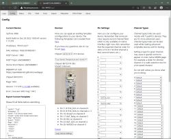
    Screenshot of the OpenBK WiFi thermometer configuration.

    We click on "Reboot" . After restarting, this page will display the SHT30 sensor readings and battery voltage.
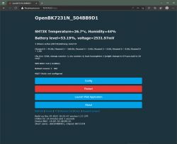
    OpenBK7231N user interface displaying temperature, humidity, and battery level information

    It`s time to connect to Home Assistant. We must have an MQTT broker running in it (or a separate one) with which the thermometer will connect. First things first…
    Click again "Config" , and then "Configure General/Flag" and we mark the flags there 2 and 35 , and then click on "Submit" and "Save" . And we go back to the main configuration page.
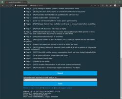
    Screenshot of OpenBK configuration for SHT30 sensor

    I recommend entering "Configure IP" and enter there the IP address that the thermometer should use. This will speed up the connection a bit after waking up, which will save the battery. However, this is not necessary.
    The next option that is worth changing is the name of the thermometer. This is also not necessary, but having several of them makes it easier to figure out which one it is. To do this, click on "Configure Names" .
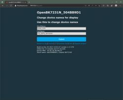
    OpenBK7231N device name change interface.

    Now I recommend clicking on the main page again "Reboot" so that the thermometer starts up with the new settings. And we continue to configure, we will connect to MQTT. We go in "Config" "Configure MQTT" and enter the parameters of our broker, address, port and login. Here we also change the name under which the thermometer is to be reported to a more user-friendly one.
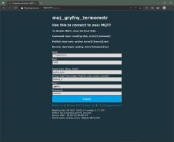
    Screenshot of MQTT configuration for WiFi thermometer

    We return to the home page, if the MQTT configuration is correct, new information will appear on it "MQTT State: connected" .
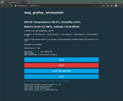
    App screen of WiFi thermometer moj_gryfny_termometr with temperature and humidity readings

    All that`s left is to add the thermometer to Home Assistant. Then we enter the configuration again "Home Assistant Configuration" and click on "Start Home Assistant Discovery" .
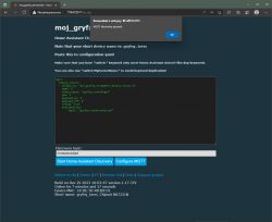
    Home Assistant configuration window for WiFi thermometer with SHT30 sensor

    The device should be detected and displayed in Home Assistant.
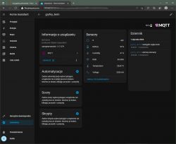
    Screenshot of Home Assistant interface showing device information.

    This could be the end of setting up the thermometer, but having the thermometer on all the time will drain the batteries even within a day. Therefore, it is very important to put it to sleep and wake it up only at certain times to send data. I wake mine up about every 15 minutes. For this you need an appropriate script, which I provide below.
    If we have closed the thermometer page, we must enter it again. And we click again "Launch Web Application" .
    Let`s go to the card "File System" . Where we will create the autoexec.bat startup file.
    Click on "Create file" and in the window that appears, enter the name "autoexec.bat" . Then click on the name of this file to launch the editor. Paste the script below into it and confirm "Save" . Now, after restarting the thermometer, it will be executed in a loop every time.
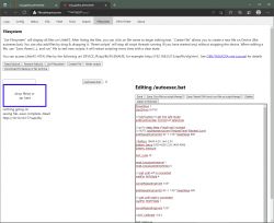
    Screen of autoexec.bat file editor in thermometer management system.

    //wlaczenie oszczedzania energii
    PowerSave 1
    
    //wlaczenie sterownika do obslugi SHT30
    startDriver SHT3X
    
    // przytrzymanie przycisku wymusi tryb serwisowy
    addEventHandler OnHold 20 SafeMode
    
    // wlaczenie licznika ktory uspi modul w przypadku braku lacznosci wifi
    addRepeatingEventID 60 -1 1337 DeepSleep 600
    
    //kalibracja i pomiar 18650 4.2V, min 2.5V
    Battery_Setup 2500 4200 2.29 2400 4096
    battery_measure
    
    SHT_cycle 15
    
    mqtt_broadcastInterval 1
    mqtt_broadcastItemsPerSec 5
    
    // oczekiwanie na polaczenie z wifi
    waitFor WiFiState 4
    
    cancelRepeatingEvent 1337
    
    //to samo co wyzej tylko teraz uspienie przy braku polaczenia mqtt
    addRepeatingEventID 30 -1 1337 DeepSleep 600
    
    // oczekiwanie na polaczenie z mqtt
    waitFor MQTTState 1
    
    cancelRepeatingEvent 1337
    
    //jesli SHT przeklamuje mozna wprowadzic korekty
    //SHT_Calibrate -0.8 2
    
    SHT_Measure
    delay_s 1
    
    publishChannels
    delay_s 5
    
    //glebokie uspienie na 15min
    DeepSleep 875


    3. Additional housing for the 18650 cell.
    As I wrote at the beginning, I replaced the power supply in my thermometers with a 18650 battery with a capacity of 3500mAh, which lasts much longer than AAA batteries (or accumulators).
    I drew the housing in one of the popular 3D design programs and printed it from white PLA filament manufactured in Poland. If you want a more resistant print, you can consider printing from PET-G.
    To download: obudowa186...mometr.zip Download (42.55 kB)

    I printed it on a delta printer that I once made based on a design from the Internet. You can find more about it on the popular forum about 3D printers – Reprapy.pl forum : https://reprapy.pl/viewtopic.php?p=138698#p138698
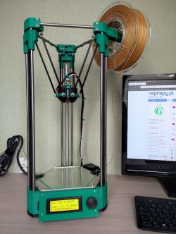
    Delta 3D printer with green parts on a desk next to a monitor.

    I won`t go into much detail about how to print a casing, because each printer is different and you need to select the parameters for it. I will only add that you should print with supports and pay attention to whether the slicer (the program that prepares the file for the printer) also creates supports under the protrusions for mounting the thermometer.
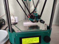
    Delta 3D printer printing a plastic enclosure.

    So we already have a printed casing cleared of supports. In addition, you will need a basket for the cell and thin cables.
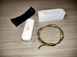
    Components for assembling a WiFi thermometer: a case, battery holder, sensor, and wires

    Before inserting the basket into the housing, we bend its legs and solder the cables to them. I also recommend squeezing the spring plates because it is very difficult for the battery to fit into the new baskets, which also makes it difficult to remove it when the basket is already in the housing.
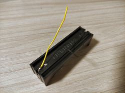
    Battery holder with attached yellow wire.

    Insert the basket into the housing, making sure that the cables fit into the grooves. And the basket was blocked by locks.
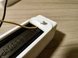
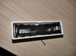
    18650 battery holder with wire Interior of a plastic case with a holder for a 18650 battery.

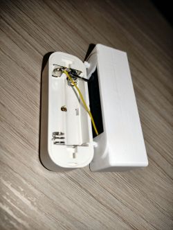
    We still need to whiten the plates in the thermometer and solder the cables from the basket to them. The baskets have polarity markings + and -, it is worth paying attention to them when soldering. I recommend lightly scraping the soldering areas and applying flux paste, then the tin will easily catch.
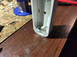
    Interior of thermometer casing with battery compartment. Open case of a white thermometer with two springs and a yellow wire inside, next to an additional battery housing.

    Now just assemble the whole thing, insert the battery, paying attention to the polarity, and we have a ready thermometer!
    WiFi thermometer on a 3D-printed base

    I have been testing thermometers with this power supply for several months, initially I sent data via HTTP, now I am trying my hand at Home Assistant. During this time, changing the power supply did not damage any of them.

    /note to the forum administration, due to the increasing popularity of 3D printers, it would be good to add the ability to upload attachments in stl format/

    Cool? Ranking DIY
    Do you have a problem with Raspberry? Ask question. Visit our forum Raspberry.
    About Author
    @GUTEK@
    Level 31  
    Offline 
    @GUTEK@ wrote 1533 posts with rating 324, helped 161 times. Live in city Gliwice. Been with us since 2005 year.
  • ADVERTISEMENT
  • #2 20888008
    gulson
    System Administrator
    Thank you very much for sharing your modification. Nice idea with changing the power supply, which significantly extends the life and can be recharged :)
    If you give me the parcel locker, I will send you a small gift useful for future projects ;)
  • #3 20888073
    speedy9
    Helpful for users
    Well, I wonder how long this thermometer will last. Theoretically, it has an acceptable power supply of 3.3-3.6V. Which would make the 2xAAA power supply rather poor as well. In fact, I have never measured the voltage of "discharged" batteries from it.
    I powered mine with a 2200mAh LiPo with a 3.3V converter. The downside of this is that we lose the battery level indication in the application. And it`s still not enough for long. These thermometers work much better in the Zigbee version. The batteries last a very long time. I have had such a thermometer in the garden since spring and it currently shows 95% of the battery.
  • ADVERTISEMENT
  • #4 20888397
    p.kaczmarek2
    Moderator Smart Home
    The decisive factor influencing how long the cells will last is the frequency of data reporting (waking up from deep sleep), and this depends on the configuration in the program, so basically everyone can choose the golden mean for themselves. Worse, if the product was without a firmware change, then we would have no control over how often it wakes up. Or at least some ready-made solutions do not allow us to do this.

    Battery life can also be improved by reducing the time the device wakes up, e.g. by setting a static IP address.

    An interesting experiment would be to implement such a sensor on, for example, the MCP9808 system, which, if memory serves me correctly, can wake up the MCU itself if the temperature goes beyond a given range. You could set the range to e.g. 2 degrees and report only actual temperature changes to the server...
    Helpful post? Buy me a coffee.
  • #5 20888761
    metalMANiu
    Level 21  
    I have a similar or the same sensor. When reporting every minute, the batteries discharged in 3 days. Now I have reports every 30 minutes and it`s been three months on one battery.

    The current reporting frequency is ok. The sensor measures the temperature in the living room and rarely changes by more than 0.5° per hour.
  • #6 20889181
    pawel250101
    Level 12  
    Once your friend has access to a 3D printer, you could go a step further and design a housing for the cell with room for electronics. It looks a bit strange at the moment.
  • #7 20889284
    @GUTEK@
    Level 31  
    p.kaczmarek2 wrote:
    Battery life can also be improved by reducing the time the device wakes up, e.g. by setting a static IP address.

    And what does it look like with flag 37? I checked it and somehow I didn`t notice any difference in connecting to Wi-Fi. Should the device connect significantly faster and does it even work in this case?
    I also noticed that even though flag 35 is enabled, if I restart Home Assistant, it does not show the values until the thermometer updates them. Is there anything else that needs to be changed so that the last value is always displayed?

    metalMANiu wrote:
    I have a similar or the same sensor. When reporting every minute, the batteries discharged in 3 days. Now I have reports every 30 minutes and it`s been three months on one battery.

    The current reporting frequency is ok. The sensor measures the temperature in the living room and rarely changes by more than 0.5° per hour.

    I can`t say yet how long the battery will last, but I`m also considering extending the sleep time. As you write, the temperature in the house does not change that quickly.
  • #8 20889706
    kuncy7
    Level 9  
    speedy9 wrote:
    Well, I wonder how long this thermometer will last. Theoretically, it has an acceptable power supply of 3.3-3.6V. Which would make the 2xAAA power supply rather poor as well. In fact, I have never measured the voltage of "discharged" batteries from it.
    I powered mine with a 2200mAh LiPo with a 3.3V converter. The downside of this is that we lose the battery level indication in the application. And it`s still not enough for long.

    I have a similar one and it currently works for 35 days on the original firmware, the battery still has 35% (whatever that means).
    The measured voltage is 2.5V. In the manual they write something about 2.5V that it is "Low power undervoltage".
    In fact, this "converted" thermometer also shows strange voltage and percentages for 18650: ~2500mV and 52%??
    Unless the screenshots were still taken on 2xAAA.

    I used Rpi3 and the DietPi system (based on Debian) to install Cloudcutter and get Cloudcutter to work properly
    on WiFi from the Rpi3 board, I had to remove the "WiFi" section from the "/etc/network/interfaces" file, otherwise "nmcli" could not communicate with the card.
  • #9 20889717
    @GUTEK@
    Level 31  
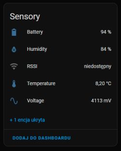
    Don`t be fooled by this screenshot. It was made to show the thermometer detection by HA. And I think so, there were some AAA batteries put in there back then.
    To correctly display the voltage and charge percentage, the battery calibration script "Battery_Setup 2500 4200 2.29 2400 4096" must be loaded - Battery_Setup [minbatt][maxbatt][V_divider][Vref][AD Bits].
    Screenshot of a sensor panel displaying battery status, humidity, temperature, and voltage information.
  • ADVERTISEMENT
  • #10 20890553
    etezet
    Level 26  
    speedy9 wrote:
    Well, I wonder how long this thermometer will last. Theoretically, it has an acceptable power supply of 3.3-3.6V. Which would make the 2xAAA power supply rather poor as well. In fact, I have never measured the voltage of "discharged" batteries from it.


    For me, when reporting every hour, it takes about half a year.
  • #11 20890733
    speedy9
    Helpful for users
    This is strange, because mine lasted about a month on batteries with hourly reporting. Reporting in the Tuya application is hourly, although samples are collected more frequently and the result is averaged from what I remember. A more frequent report appears only when the temperature changes significantly.
  • #12 20890944
    p.kaczmarek2
    Moderator Smart Home
    https://github.com/openshwprojects/OpenBK7231T_App/blob/main/docs/flags.md
    @GUTEK@ wrote:

    And what does it look like with flag 37? I checked it and somehow I didn`t notice any difference in connecting to Wi-Fi.

    https://github.com/openshwprojects/OpenBK7231T_App/blob/main/docs/flags.md

    At the beginning of work on the firmware, contributor @btsimonh discovered that connecting to WiFi right after reboot causes problems for some users and introduced an artificial delay of probably 3 seconds or so, this flag eliminates this delay. Some time later we updated LWIP with @valeklubomir and improved multithreading, so now we usually recommend turning on this flag, it should speed up the connection by 3 seconds or so.
    Generally, in an ideal world we would do this Always connects immediately to WiFi, but we have no way to check every device and every possible combination, and we don`t want to spoil anything for users, that`s why this option is as a flag...

    The situation is similar with PowerSave - it is not enabled by default, although it is recommended. I was going to turn them on by default, but there were two reports that PowerSave killed someone`s device and turned on Safe Mode, and we were unable to replicate the problem on our side.

    If you have a large number of users, you just have to be careful not to introduce an "update" that massively breaks something, although we are protected by Safe Mode (after five failed reboots), but we still try to be careful

    @GUTEK@ wrote:

    I also noticed that even though flag 35 is enabled, if I restart Home Assistant, it does not show the values until the thermometer updates them. Is there anything else that needs to be changed so that the last value is always displayed?

    [HASS] Deactivate avty_t flag for sensor when publishing to HASS (permit to keep value). You must restart HASS discovery for change to take effect.

    What you wrote is fully consistent with expectations, because removing the avty_t topic simply prevents the sensor from disappearing from HA when it goes to sleep (it does not turn into unavailable). I think you should also enable this option retain , try it and let me know.
    Helpful post? Buy me a coffee.
  • #13 20891376
    CMS
    Administrator of HydePark
    speedy9 wrote:
    when reporting hourly


    It doesn`t make sense, for example, if you want to set the room to be heated to a given temperature and monitor it, the hysteresis will be unacceptable.
  • ADVERTISEMENT
  • #14 20891452
    p.kaczmarek2
    Moderator Smart Home
    It depends on who is measuring for what purpose... if only 1 hour is good.

    By the way, after changing the firmware, you can simply connect one of the supported temperature and humidity sensors, even the simplest DHT11, to basically any supported IoT product and then use, for example, a simple, network-powered relay module as a sensor. Of course, you must remember not to measure the temperature in its housing (because there will be some distortion), but it is still worth remembering that it is possible.

    Just set the GPIO and even with Home Assistant Discovery, HA itself will discover the presence of the sensor:
    Screenshot of GPIO configuration with DHT11 sensor settings.


    Helpful post? Buy me a coffee.
  • #15 20893032
    speedy9
    Helpful for users
    >>20891376
    In practice, there is no problem with this
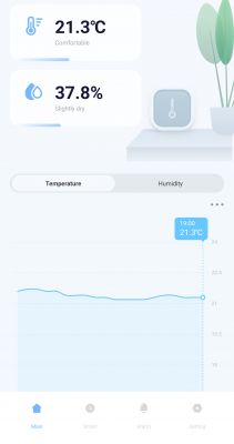
    App interface showing temperature and humidity.
  • #16 21551107
    jafocol
    Level 1  
    Good morning, I installed everything and it worked except the sht30 sensor wasn't reading data, so I flashed the OTA version OpenBK7231T_1.18.101.rbl
    and it's stuck like a brick. Please help me with how I can fix this.

    Edit: I think I found the error, I flashed a version T to N chip once!!

    Added after 1 [hours] 14 [minutes]:

    I'm flashing another one and I have this problem in the logs been loaded with
    CMD:lfs is absent
    Info:MAIN:Driver SHT3X is not known in this build.
    Info:MAIN:Available drivers:
    In which compilation can I use the sht30 driver?
  • #18 21551267
    @GUTEK@
    Level 31  
    Upload version 1.18.11 - this is the latest with the SHT3X driver added.
  • #19 21583370
    p.kaczmarek2
    Moderator Smart Home
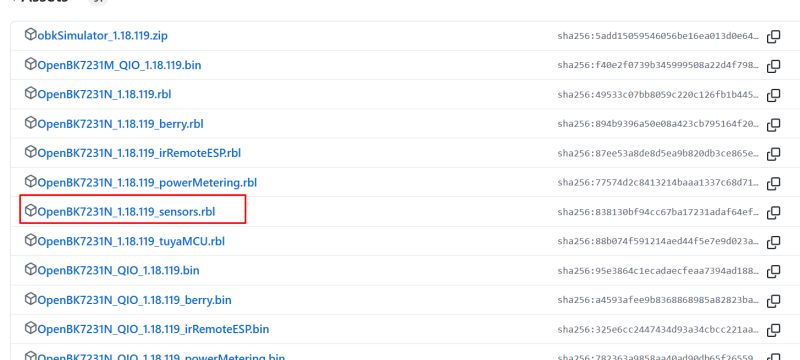
    SHT3X is available from today in a separate package in Relases - the sensors version. This is the OBK with drivers enabled for multiple sensors but with TuyaMCU and LED disabled.
    Screenshot of the GitHub page showing the “Releases” section for the OpenBK7231T_App project. .
    https://github.com/openshwprojects/OpenBK7231T_App/releases
    Helpful post? Buy me a coffee.

Topic summary

The discussion centers on modifying WiFi thermometers equipped with the SHT30 sensor and BK7231N chipset to improve power efficiency and integrate with Home Assistant. The original AAA battery power supply is replaced with a rechargeable 18650 lithium-ion cell, despite the risk of exceeding the recommended 3.6V maximum voltage of the BK7231N system (fully charged 18650 cells reach 4.2V). Firmware changes involve uploading OpenBK7231T custom firmware, which supports multiple sensors including SHT3X, and enables configuration of reporting intervals to optimize battery life. Users report varying battery longevity depending on reporting frequency, with hourly reports lasting from one month to half a year, and longer intervals extending battery life further. The use of flags such as flag 37 can reduce WiFi connection delays, improving device responsiveness. Battery voltage and charge percentage readings require calibration via a battery setup script. Integration with Home Assistant is facilitated by Home Assistant Discovery, allowing automatic sensor detection. Challenges include firmware compatibility with the SHT30 driver, resolved by using specific OpenBK7231T firmware versions (e.g., 1.18.11 and later sensor-enabled releases). Additional hardware modifications include 3D-printed housings for the 18650 cell to fit within the thermometer casing. Alternative sensor suggestions include MCP9808 for event-driven wake-ups to further reduce power consumption. The discussion also touches on network configuration tips for stable WiFi operation on Raspberry Pi systems running Cloudcutter.
Summary generated by the language model.
ADVERTISEMENT