Elektroda.com
Elektroda.com
X

LED weather station with NTP clock and calendar

efi222 13398 63
This content has been translated flag-pl » flag-en View the original version here.
  • LED weather station with NTP clock and calendar

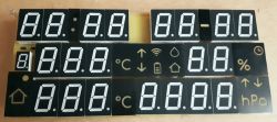
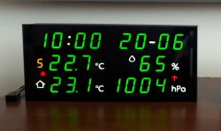
    The title picture is probably a bit familiar from my previous topic about pictograms.
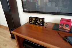
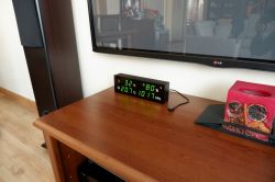
    Today the device is ready. Generally available weather stations have one thing in common - the LCD display. It has its advantages and disadvantages. When it comes to the readability of these panels, it is different. So I decided to build a station using seven-segment LED displays. The height of the figures in the design is 2.5 cm. Visibility is excellent from a distance of several meters in the dark as well as in bright rooms and at large viewing angles.
    The front dimensions of the device are 27.5 x 12.5 cm.
    The panel displays the current time, day of the month, month, temperatures from modules 2 to 9, "home" temperature, humidity, atmospheric pressure, temperature and pressure trend arrows. As well as alarm icons - lack of communication with the module, low battery status of the module and others.
    I made several such stations in different versions, for family and friends. Also versions without clock and calendar. Pictures below.
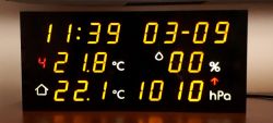
    LED weather station with NTP clock and calendar

    The device is fully configurable. You can set the number of sensors, the action of measurement tendency arrows, panel brightness, time of automatic switching of measurements, etc.
    The transmission interval can be set in the measuring modules.

    Device Description.
    The time and date are downloaded from the Internet from publicly available NTP servers. The time is updated in full hours.
    Support for up to 9 measurement modules (temperature and humidity measurement).
    Switching the module number on the display is done using the IR remote control.
    The station remembers 4 orders of any pilot. These can be, for example, unused buttons on the remote control of our home equipment. They can also be single buttons from 4 remote controls. The RC5 and RC6 remote controls are not suitable for this. Although stubborn, it is possible to expand the software to support them.

    Pilot commands:
    1 - switching measurements down
    2 - switching measurements up
    3 - automatic switching (time set in station configuration)
    4 - display blanking.

    As the LED displays glow quite strongly in the dark, I used brightness adjustment depending on the ambient light. This adjustment is configurable according to your preferences. Two brightness points are set. Contractual minimum and maximum. Display brightness is set to minimum in low ambient light. Similarly, in bright light, the maximum brightness is set. The device remembers the brightness of the environment and the level of illumination of the display. The entire range of brightness changes in 30 levels. The brightness of the display changes exponentially. To the eye, such changes are more linear.

    The station is powered by a 12V 1.5A plug power supply. Power consumption depends on the brightness of the display and ranges from 1 to 5W.

    Measurement module.
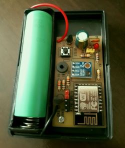
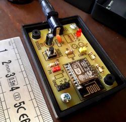
    The ESP12 module is responsible for radio communication between the module and the station. (ESP8266).
    I used the Espressif ESP-Now protocol for data transmission. It allows you to send data quickly. Waking up the system, sending the measurements and going to sleep again takes about 0.3 seconds. During sleep, the power consumption is between 30 and 100 uA. This value depends on the quality of the used LDO stabilizer and other modules. I used the DS18B20 as the temperature sensor, and the HTU21D as the humidity sensor. The whole is powered by one 18650 cell. When sending measurements every minute, the battery with a capacity of 2000 mAh is sufficient for approx. 6 to 7 months of operation. In subzero temperatures, this time is shorter. (I did the tests without the LDO stabilizer). It should be better with the stabilizer.

    Configuration of measuring stations and modules is done via a web browser.
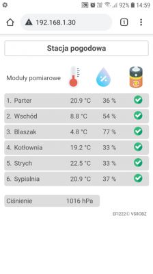
    The pictures show the configuration of the station and sensor modules. Regardless of displaying the measurements on the panel, it is possible to view all the measurements on the local website. Its address (IP) is available on the configuration page, after proper connection to the wifi network.

    settings
    LED weather station with NTP clock and calendar

    screen shot of the phone

    LED weather station with NTP clock and calendar
    In case of problems with the radio range from the modules to the stations over longer distances, I developed something like a repeater. It significantly increases the range.

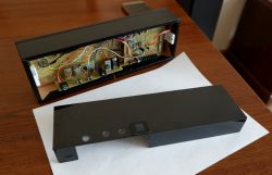
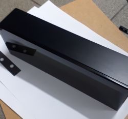
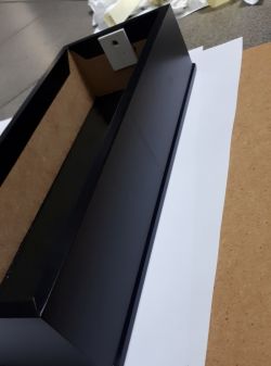
    The station housing is made of 6mm MDF board with tinted glass on the front. Black Antisol, 6mm thick. MDF is covered with a black matt veneer. The rear wall is cut from black polystyrene with a thickness of 1mm.

    A description of the action.
    As I wrote above, the measurement modules send data from sensors to the station using the Esp-Now protocol. The ESP8266 receiver receives this data and sends via UART to the Atmega64. It also generates the station configuration website and the measurement website.
    Atmega64 deals with displaying data on LED displays, calculating the trend of measurement data, enabling alarms, etc. The IR receiver is connected to the Atmega8, which sends processed data from the remote control to Atmega64 via 4 data lines.

    Alarms:
    Alarm for lack of connection between the module and the station. The wifi icon is on. The panel automatically selects the number of the module that has no connection and the pictogram "C" blinks next to the temperature digits.

    Low battery voltage alarm. It starts below 3.3 V. The battery icon is on and the number of the module with the discharged battery is selected. Pictogram "C" flashes next to the temperature digits. If the voltage drops below 3V, the module falls asleep "forever"

    The software is written in the Arduino Ide environment and is a set of codes available on the Internet and own. I am not a professional programmer, so I am asking for the understanding of the professionals, but I would love to hear your comments about the sources.
    Pictures do not reflect the actual appearance. It is difficult to photograph glowing LEDs.
    And that's it, in a nutshell :)
    I attach manuals and sources with diagrams.

    The display board. One-sided. Unfortunately, you need to do about 150 guides on it.
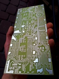
    LED weather station with NTP clock and calendar

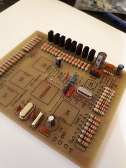
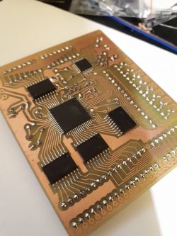
    Atmega64 board and drivers
    LED weather station with NTP clock and calendar

    LED weather station with NTP clock and calendar

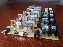
    power supply and receiver boards
    LED weather station with NTP clock and calendar

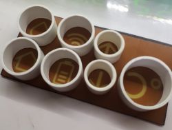
    pictogram covers
    LED weather station with NTP clock and calendar

    LED weather station with NTP clock and calendar

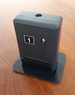
    measuring module
    LED weather station with NTP clock and calendar

    LED weather station with NTP clock and calendar

    "repeater"
    LED weather station with NTP clock and calendar

    general view of the station
    LED weather station with NTP clock and calendar

    LED weather station with NTP clock and calendar

    LED weather station with NTP clock and calendar

    LED weather station with NTP clock and calendar

    I added the missing two softs to the Atmega64 and the IR receiver

    Cool? Ranking DIY
    Do you have a problem with Arduino? Ask question. Visit our forum Arduino.
    About Author
    efi222
    Level 13  
    Offline 
    efi222 wrote 166 posts with rating 550. Live in city Toruń. Been with us since 2019 year.
  • #2
    And!
    Admin of Design group
    The case made of veneered MDF turned out very well, maybe you can write something more about processing and preparation?
  • #3
    khoam
    Level 42  
    Very nice workmanship. Congratulations!

    efi222 wrote:
    In case of problems with the radio range from the modules to the stations over longer distances, I developed something like a repeater. It significantly increases the range.

    Could you write something more about the operation of this "repeater"?

    The humidity sensor is inside the housing of the measuring module - does it not affect the measurement?
  • #4
    efi222
    Level 13  
    ESP8266 in the weather station works in AP and station mode.
    Station mode connects to local wifi network. AP mode is hidden. In this mode, it receives data from sensor modules after ESP-Now. The "Repeater" works in station mode and as a Combo in ESP-Now mode. Its station mode connects to the weather station AP via IP as a wifi client. And as Combo in ESP-Now mode, it receives data from modules and forwards it to AP in ESP_Now mode. If the station is closer in range, then only it receives data from the modules, if the repeater is closer, it receives it and forwards it. If the data reaches the weather station and the repeater, the weather station receives duplicate data, which is not a problem.
    It's a little crazy :)
    The sensor housings are ventilated. I did not notice that it had an effect on the humidity measurement.
  • #5
    krzbor
    Level 25  
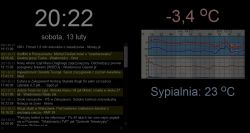
    Well done. In the bedroom, I had a reading of internal and internal temperature and pressure. The system is based on the HD44780 display. It worked for many years, but the aesthetics of this solution was poor. I have already bought a larger TFT display to build a new chip - data was to be downloaded from the server via esp8266. I wanted a large size so that readability would be good at a distance. Ultimately, however, I did it differently - I took an old tablet from my son, which had a lockable cover. I removed the material so that only the plastic frame remained. From the back, I attached a piece of wood with a heat-glue as a leg that also provides the right angle of inclination. Of course, the frame includes a tablet that is permanently connected to the power supply. For aesthetics, the micro USB plug is angled. Now it's time for software - there is no philosophy here - it's just a website. Use the property of Chrome for Android - the ability to pin a page to the home screen. This is very important as there is no address bar after launch. Here is the result (screen content):
    LED weather station with NTP clock and calendar
    The image is dim because the astronomical clock has detected the night. On the website I present the date, time, Google RSS, weather forecast and of course the outside and bedroom temperature, plus additional information about the alarm.
    Dimming is a big problem (the tablet didn't have one). The astronomical clock solves the problem to a large extent.
  • #6
    efi222
    Level 13  
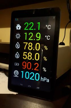
    I also used to "play" with an old tablet, but in combination with Virtuino. However, this program is only for Android. In the code of the published station, you can add the Virtuino library and send data to a tablet or phone. I made such attempts. However, the web browser is cross-platform.

    Such attempts ...
    LED weather station with NTP clock and calendar

    When I started to play with electronics, you could only dream about LCD displays. But I have a great fondness for seven-segment displays and I just like their lighting :) .

    @And! . I will try to prepare something about MDF boxes. I even have some photos of their construction somewhere.
    Information for those who downloaded the files. The first package is incomplete and I have also added some Atmega64 and IR receiver software.
  • #7
    krzbor
    Level 25  
    The seven-segment displays are interesting and have their own atmosphere. However, when you look at your tiles, you can see that you need to put a lot of work into such a device. Leaning on a tablet or unused phone with a large display (eg J5 or J7) is extremely easy. All you need is HTML + javascript skill. It is important that these are TFT matrices, not OLED or AMOLED, which have a beautiful image, but lower durability and are rather not suitable for continuous image display. A particularly nice effect is achieved with black tablets and phones. You can then use a black background - everything looks very nice and uniform. You can also see it on your example.
  • #8
    efi222
    Level 13  
    As for the simplicity of the layout, I agree with you 100%. Only one condition has to be met - we have an old tablet at home. When it comes to the black background on TFT, it is rather a moot point :) . Although tablets and phones probably have better black and viewing angles than factory weather stations. A colleague ordered a LED station from me and put the Chinese one with a color TFT in the wardrobe. Underwater - viewing angles. Apparently a massacre. Well, not everyone is bothered by it ...
    Visitors at home ask where I bought such equipment, because they would also like to buy it. So something's up.
    The photos do not reflect the actual appearance of these stations. It is very difficult to photograph glowing LEDs. In the photos, the colors are falsified and that's it.
    Besides, repeatability. Virtually every structure I build, and even more so I want to show the world, I try to do it in such a way that I can build another one, or someone else could do it.
    I'm just curious if anyone will jerk off to this construction on the subject, because I have been working with it since then. Although I managed to build 6 pieces. So I guess you can ... :)
  • #9
    ArturAVS
    Moderator HP/Truck/Electric
    efi222 wrote:
    Underwater - viewing angles.

    How about a VFD display? Here the viewing angles beat TFT at the start.
  • #10
    Gienek
    Level 37  
    I am impressed with the idea, the aesthetics of execution and the description itself. Certainly, many Forum participants would like to try to repeat the construction, because the materials provided encourage them to do so. Does the colleague, in addition to the presented diagrams, provide for sharing any materials related to PCBs?
  • #11
    efi222
    Level 13  
    I use Sprint Layout 6 to draw PCBs. But I think there is some viewer to preview and print PCBs from this program. After that, I don't see a problem with sharing the tiles :) . I just don't know about the plate for displays. The ones used in the project are green AS-10016BMG-B or yellow AS-10016BMY-B and smaller ones to the module number - AS-05613BMR or AS-05613BMY.
  • #12
    Gienek
    Level 37  
    Sprint Layout 6 is quite easy to find on the Internet and a browser is not needed. In addition, Sprint Layout 6 has the ability to export Gerber files. Displays (or replacements) are also available. The conclusion is that if you share files from your program, they can be very helpful for those willing to make a station according to your project.
  • #13
    Crayou
    Level 13  
    Functional and aesthetic design - congratulations. I am a fan of self-made weathercats :)
    Currently I am discovering Virtuino, I am in possession of an old tablet, but I have doubts - is a permanent connection to the power supply safe?
  • #14
    efi222
    Level 13  
    A colleague of the bush has a weather station on the tablet that is on. You'd have to ask him how long he has it running. :)
    Somewhere I read that someone wanted to run the tablet without a battery on the power supply, but without success.
  • #15
    krzbor
    Level 25  
    Crayou wrote:
    Functional and aesthetic design - congratulations. I am a fan of self-made weathercats :)
    Currently I am discovering Virtuino, I am in possession of an old tablet, but I have doubts - is a permanent connection to the power supply safe?

    Tablets have a charge control. The battery will not be overcharged. I don't know how such a constant charge will affect its durability and capacity, but that doesn't worry me. I have had one tablet permanently connected to the power supply for about a year, but it is lit by a proximity detector - it is off all the time. The one for the bedroom is permanently lit, but I've had it that way for a couple of weeks. I am more wondering how the matrix will handle it. In theory, it should work for a very long time - the backlight is "screwed" on (even the black screen is lit at night, and this is a bedroom) - the LEDs should last a long time. For liquid crystals, it shouldn't make much difference either, but we'll see :)
    Viewing angles can be very good - you need to choose a tablet with an IPS matrix. For people who want to look like LED displays - Chrome and other browsers support canvas. So you can paint what you want on the page - nice display segments too. Well, it's just an emulator :) However, I think that with a good IPS matrix and during the day it will not be easy to recognize it at first glance, although that something is wrong will reveal the thickness of the device. When it is dark, unfortunately - the black background is not perfectly black and the "cheating" will be visible. I even found a library: Link or such: Link
  • #16
    efi222
    Level 13  
    Nowadays, it is difficult to say anything about the durability of LEDs. This also applies to seven-segment displays. Led strips are not very durable. And yet the standard current of 20mA flows in these LEDs. In 1990, I was building digital thermometers on the ICL7107. The displays are still lit today, but these are different times and elements then. Everything is corporate. And now? The great unknown...
  • #17
    varaktor
    Level 18  
    Once, in my weather station, I used modules on EPS8266, which from time to time sent measurement results to the server, but it turned out that the entire ESP8266 module heats up the sensor next to the board very effectively.
    Now I have a better solution: you can buy weather stations with three sensors that transmit measurement results at 433.92 MHz from time to time. The sensor itself for 2xAA with temperature and humidity measurement can be purchased for PLN 30-40. Signals from the detectors can be received on the RPi with the rtl-sdr donglem, there is software ready for this (rtl_433).
  • #18
    efi222
    Level 13  
    It was enough to put ESP to sleep after transmitting the data. The average power consumption when sleeping is about 70uA. And nothing gets hot, because what ... :)
  • #19
    Crayou
    Level 13  
    efi222 wrote:
    Tablets have a charge control. The battery will not be overcharged. I don't know how such a constant charge will affect its durability and capacity, but that doesn't worry me.

    This issue does not bother me either. Lenovo tablet, so not some "bush" but nothing of the daily activities will not drag you, so its last use in life would be ideal. What scares me more is the vision of a swollen battery or some kind of ignition ...? Have I exaggerated my imagination?
  • #20
    khoam
    Level 42  
    Crayou wrote:
    What scares me more is the vision of a swollen battery or some kind of ignition ...? Have I exaggerated my imagination?

    I guess a bit like that ;) About 5 years ago I purchased a (very) cheap Huiwei 7 inch tablet. For similar purposes. To this day, it "runs" on the power supply, because on batteries it will not last longer than a few minutes :)
  • #21
    efi222
    Level 13  
    I do not have too many photos of gluing the housing, but there is some outline.
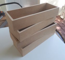
    Description of gluing the housing with MDF.
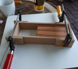
    There is no great philosophy here. After cutting the elements, I glue them together and press them until they dry or the glue is stably caught.
    LED weather station with NTP clock and calendar
    After the glue is completely cured, I sand it with a 180 gram paper and then ground it with nitro Kapon varnish. After the varnish has dried, I sand it again and I no longer ground it. The frame glued in this way is quite delicate. It will gain stiffness after sticking the windshield.

    LED weather station with NTP clock and calendar
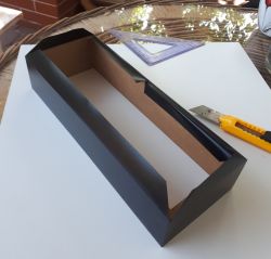
    Before sticking the veneer, the surface must be well dusted. The veneer strip should be wider enough so that it protrudes about 0.5 cm on one side and on the other side with a margin for folding the veneer inside. We "unfold" the veneer along the frame. At the corners, I cut it at a 45-degree angle and wrap it inside. I heat the veneer with a hair dryer. It works better. I cut the stock on the other side with a paper knife. Warning! Once applied, the veneer cannot be torn off. If necessary - after tearing the frame off, you have to prepare it anew (grinding).
    LED weather station with NTP clock and calendar


    Attaching the windshield.
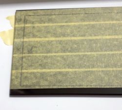
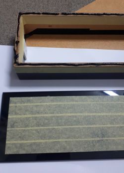
    I cover all glass with painter's tape. I put an MDF frame against it and outline its internal outline on the tape
    LED weather station with NTP clock and calendar
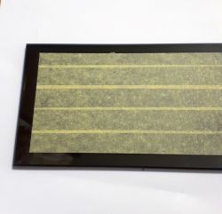
    I cut the tape with a knife as shown in the picture. The remaining paper tape should not go under the frame.
    LED weather station with NTP clock and calendar
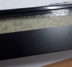
    I cover the frame with painter's tape as shown in the picture and put black silicone on it. It should be spread not too thick over the entire mdf surface. But no fear. Anyway, the excess will go beyond the outline of the frame when pressed against the glass.
    LED weather station with NTP clock and calendar
    I put the frame to the glass and remove the excess silicone.
    LED weather station with NTP clock and calendar
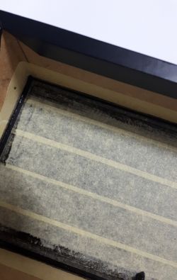
    Inside, it can be done with a wooden stick.
    LED weather station with NTP clock and calendar
    Remove the remaining silicone with a paper towel and denatured alcohol or spirit :) . Inside, sticks with cotton balls are also useful.
    LED weather station with NTP clock and calendar

    LED weather station with NTP clock and calendar

    Caution!. The frame is a bit unstable in the plane on fresh silicone. Leave everything to dry, preferably with the glass facing down.
  • #22
    And!
    Admin of Design group
    @ efi222 as for me, this is material on a new topic, you can add a little more.
    Then it will not disappear as an answer to the topic, but will be available as a "own topic" tutorial.
    Of course you can link to this topic about the station to show the result.
  • #23
    Piottr242
    Level 23  
    A very nice design.
    efi222 wrote:
    I made several such stations in different versions, for family and friends. Also versions without clock and calendar.
    [...]
    The display board. One-sided. Unfortunately, you need to do about 150 guides on it.

    Why, if you were doing a few, did you not take advantage of the option of ordering a double-sided plate from JLC or a similar tiling company?

    It was the possibility of making a double-sided plate with metallized holes, something inaccessible at home, that pushed my design tests to a much higher level.
  • #24
    efi222
    Level 13  
    Well . There was such an idea, but I was looking at Polish companies for the production of PCBs and unfortunately the price was not attractive. For a single-sided 25 x 11cm display plate, there was probably something like 60 PLN per piece, with a few pieces. I will not mention two-sided. It's not cheap. Besides, in the past, you had to combine everything for the construction yourself, and it probably stayed that way :) . But maybe one day you will have to try it for the first time and order it from a professional company.
  • #25
    pier
    Level 24  
    There was no problem with running WiFi and ESP NOW on one ESP? I once read something that in order for it to succeed, you need to do some special procedures.
  • #27
    krzbor
    Level 25  
    efi222 wrote:
    You have to do a little trick. I described it here https://www.elektroda.pl/rtvforum/topic3672038-30.html#19080795
    If I understood the description correctly, if the correct connection to the same WiFi network (the same AP) was made on both ESP (master and slave), should it work after switching to ESP-NOW? This solution requires AP to be visible through both ESPs, but we don't need to know the channel (it should be the same).
  • #28
    khoam
    Level 42  
    krzbor wrote:
    If I understood the description correctly, if the correct connection to the same WiFi network (the same AP) was made on both ESP (master and slave), should it work after switching to ESP-NOW?

    As long as ESP-NOW runs on the same channel as the client. Generally, the transceiver in ESP cannot work on more than one WiFi channel at the same time. Unfortunately, you have to ensure and watch over yourself.
  • #29
    varaktor
    Level 18  
    efi222 wrote:
    Well . There was such an idea, but I was looking at Polish companies for the production of PCBs and unfortunately the price was not attractive.


    A Chinese will do it for you for 1/4 of the price and he will be polite, nice, on time and the tiles will be well made.
  • #30
    efi222
    Level 13  
    krzbor wrote:
    If I understood the description correctly, if the correct connection to the same WiFi network (the same AP) was made on both ESP (master and slave), should it work after switching to ESP-NOW? This solution requires AP to be visible through both ESPs, but we don't need to know the channel (it should be the same).

    Well, this is actually an interesting solution. You would have to test. Connect the master to the wifi network for a while. Theoretically, it should remember the network settings including the channel?
    My friend khoam probably experimented with Credentials ...