Once again - Small headphone amplifier - ty.ytka
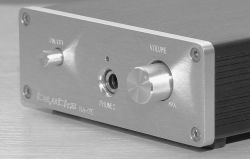 .
.
The design of this headphone amplifier, is actually an update of my earlier design presented here ( Link ).
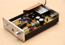
Compared to the original version, a few things have been changed. The one that is immediately apparent is the casing.
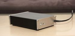
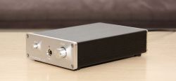
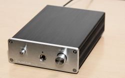
The new housing is slightly larger. Its internal dimensions are: 105 x 160 x 35mm (with external: 115 x 168 x 40mm). The dimensions of the amplifier board are: 97 x 159.5mm. So, there is now slightly more space. The board itself is now not pushed into the profile, but fixed to the underside of the case, via spacers 5mm high. From the side edge of the plate to the side wall, there is 4mm of space on each side. The area of the housing that is adjacent to the mains voltage area of the PCB has been shielded with 0.5mm thick pre-shrink. The mains cable exit from the enclosure, is sheathed in a dedicated rubber bend.
All the work involved in machining the raw case to adapt it for this project was done by myself.
The lettering was engraved, using a small, simple CNC machine.
Just to pre-empt any questions, I would like to inform you that this time the engraving was not filled with paint on purpose. The idea was for the description to be there, but relatively subtle.
Now perhaps a little about the electronics.
For those who haven't seen the previous version, let me remind you that this is a design based on Douglas Self's project on achieving higher power when connecting operational amplifiers in parallel.
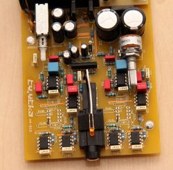
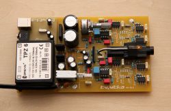
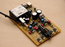
Compared to the previous version, the circuit has been slightly simplified. The amplifier section has been shortened to two stages. Why? The previous version was actually a fitting for a power amplifier realised on operational amplifiers, which I was working on at the time ( Link ). It was known that the circuit there (power amplifiers) would need more gain. However, in a headphone amplifier, such an elaborate circuit is not needed. So I decided to simplify it, resulting in only two stages remaining. The first is a parallel voltage amplifier (2 operational amplifiers) and the second is also parallel, but this time a current amplifier (4 operational amplifiers).
The rest of the circuitry, i.e. the power supply, the protection circuit, and the DAC, remained as before.
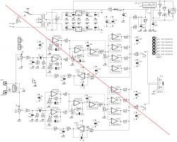 .
.
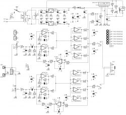
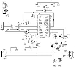 .
.
 .
.
Below are a few more photos showing the end result.
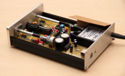
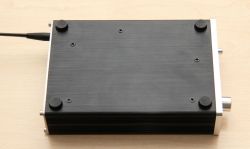
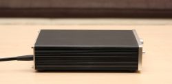

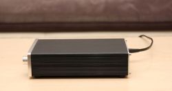
 .
.
However, I will take the liberty of posting the results of the amplifier measurements, as these will also be there, at a later date.
And one additional piece of information.
The previous enclosures have not gone to waste. They were used for other devices, which quite possibly will be presented here..


Comments
Each time, I am impressed by the aesthetics and refinement of the design. What is a U3 circuit in an oblong housing? The output protection? And a second question - do you mill the front panel in-house... [Read more]
Workmanship as usual super. Those extensions for the switch and potentiometer are reminiscent of the construction methods once used for oscilloscopes. The schematic? It's gone from very contrived to... [Read more]
Another very nice design, I'm very curious to see the measurements and how they compare to the previous, heavily developed version, how much the performance has deteriorated (or improved?). [Read more]
You, when you throw something in, it's always a masterstroke, your designs are top notch :) [Read more]
It is a pleasure to look at each of your projects, the attention to detail of workmanship is exemplary in DiY. You have improved the design by what you deemed worthy of correction. Obviously a big plus... [Read more]
You are already approaching the level at which I would spend the money to buy. A little more refinement to the lettering on the front panel and we have a commercial level of workmanship. [Read more]
I see the paper under 230V is :-) . [Read more]
I'm impressed with the design and aesthetics. It looks great and probably works just as well. I noticed a little zonk in the schematic but that's probably a Czech error. https://obrazki.elektroda.pl/5456268400_1731396564_thumb.jpg... [Read more]
Something wonderful. There is no denying that some users are waiting for the ty.tyk presentations with baked goods! I guess you haven't received the goodie kits from Elektroda yet, send a Parcel Post,... [Read more]
If I were ever tempted to build an amplifier according to this topology, I would simplify it to: https://obrazki.elektroda.pl/1127212500_1731402858_thumb.jpg . - the first stage amplifier I would... [Read more]
Thank you very much for your comments. Of course, I'm aware that the level of my projects is still not up to par with the commercial ones, but for the time being, that's all I can afford. And also... [Read more]
If I'm not mistaken, this simplified version has slightly better performance than the previous, more elaborate version, especially the THD, which is almost halved. I'm already overlooking the fact that... [Read more]
. Interesting... You must have something wrong. I would expect a lot more from analogue too. Can you give measurements of the card/interface itself? [Read more]
In fact, this version came out slightly better in the tests carried out. But this may be partly due to the slightly changed measuring conditions. It doesn't look like anything is wrong. It's just that... [Read more]
Where did you get this enclosure from? I ordered some from the net, it was supposed to have these dimensions, it arrives and here's the trick, the dimensions are given for the outside and it's not possible... [Read more]
. Today I had a moment, so I tested the original/more elaborate version (as it sits in a drawer one without a case) under the same conditions as now this revised, or simplified, one. For the line input: ... [Read more]