logo elektroda
logo elektroda
X
logo elektroda

Acoustic amplifier for those who hear differently

yego666 7032 68
ADVERTISEMENT
Treść została przetłumaczona polish » english Zobacz oryginalną wersję tematu
  • Similar topics have already been discussed on the Forum, but my device is the most mine, so I decided to share a report of its construction with those who either have hearing problems or would like to make a similar device for someone with such a problem.

    I'm not an acoustician and I don't do acoustics at work, so professionals versed in the art may find the presented device technically poor, incompatible with the art and Be at all, but it has an undeniable utility value confirmed by the person concerned, with whom I can now communicate freely.

    I know you can buy a fairly decent amplifier on the MAX9814, however, where is the fun and learning here?
    So I borrowed the base schematic from the website : Link .
    I made this device unchanged, but it had some significant drawbacks such as a very high resting current ( battery life ) and a lot of noise.
    So I decided to simulate this circuit under LTSpice, which pointed me in the direction of improvements.
    This resulted in a circuit with relatively low noise, a flat gain characteristic from about 80Hz to the limits of audibility ( probably around 10kHz ) and a negligible resting current of less than 3mA.
    The final shape of the circuit is shown in the diagram below:
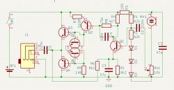
    Circuit diagram of an audio amplifier. .

    and here is a revised version of the final layout form:
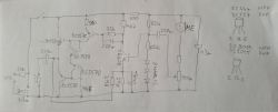
    Hand-drawn schematic of an electronic circuit on grid paper. .

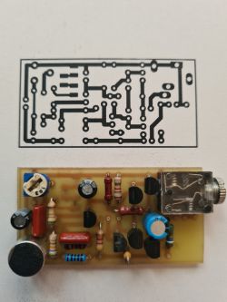
    What the layout is like everyone can see. A board was also created, of course :
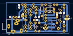
    Printed circuit board design with electronic components. .

    and then it was enhanced with the relevant electronic components:
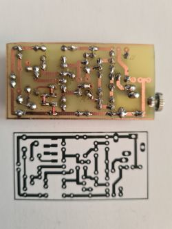
    Printed circuit board with soldered components, next to an etched PCB pattern. PCB with mounted electronic components in front of a printed circuit diagram.

    It's not a master craftsmanship, but it works and follows the schematic.
    After attaching the LiIon battery, headphones and switch, I performed tests and basic measurements.
    Actually the resting current is about 3.2mA and the noise is very negligible. The circuit picks up sounds well from about 5 metres and, most importantly, does not distort them in the audible range of sound waves. The goal has therefore been achieved.
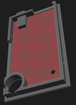
    Now only the casing remained to be made. Since I acquired a 3D printer, this is no longer a problem and instead of adapting the device to the housing I have, I make a housing for the circuit I made. Very convenient and quick, and I don't have to search for the right box.

    The box consists of the bottom and of course the top :
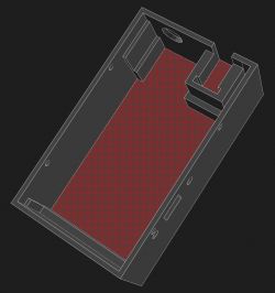
    3D model of a part of an electronic device housing Render of an electronic device enclosure with space for a printed circuit board. .

    And after printing it looks like this:
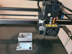
    3D printer printing a case for an electronic device. .

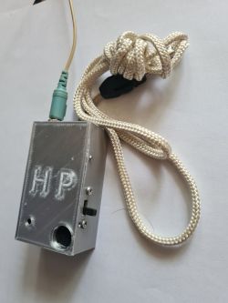
    Now the previously made layout goes into a new box :
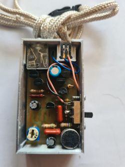
    Interior of a prototype sound amplifier in a box with electronic components. Homemade electronic device in a plastic 3D printed case.

    and that's pretty much it.
    One more thing, I originally used a BC109C transistor in the input stage, but the noise was too high, so I replaced it with a 2SC9014. The noise dropped well below the expected value, so that's how it stayed.

    I use an old power supply from a Nokia phone as a charger. The battery is charged with about 100mA through a 20 ohm resistor. Ten hours is completely sufficient to fully charge the battery. This is not the recommended way to charge LiIon batteries, but if someone wants to, they can connect an external circuit purchased from MyFriends instead of a simple phone charger..

    I use 32 ohm headphones connected in series on the output, but both 16 and 64 will work well too. Volume control is via a potentiometer on the headphone cable.

    I don't expect applause, but if this device is useful to someone, I think I'll consider the goal achieved.

    I encourage esteemed colleagues to enrich the topic with their valuable comments and ideas.

    Cool? Ranking DIY
    About Author
    yego666
    Level 33  
    Offline 
    yego666 wrote 2156 posts with rating 534, helped 239 times. Been with us since 2004 year.
  • ADVERTISEMENT
  • #2 21129479
    md
    Level 41  
    I suggest doing a little test to show that the mere fact that the 'interested person' hears better or hears at all is already something, but something will be missing. Just hide from the 'interested person' and call out to him or her and then watch carefully for his or her reaction. That person will hear, but cannot locate the source of the sound.
    In my opinion, it is essential for people with bilateral hearing impairment that such a hearing 'aid' is fully dual-channel - two microphones and two headphones. Microphones mounted so that they can locate the sound source.
    As I have approached the project of assembling something similar myself several times, I already have some thoughts. One option would be two independent amplifiers mounted in the ear cups of the headphones. A microphone and earbud mounted in one place, so that by moving the head to the right and left, the microphones pick up the signal from exactly the direction from which the user wants to hear something. There are two issues - power supply and suitably small microphones that would fit into the headphones.
    The power supply can be shared - something like a battery pendant from which the power cables go to both amplifiers. In your case, the 'pendant' sans the entire unit (apart from the headphones).
    The second issue is suitable microphones. The dream would be to get the microphones used in hearing aids.
  • ADVERTISEMENT
  • #3 21129584
    gulson
    System Administrator
    Thanks, I for one am glad to see hearing aid designs still appearing. It reminds me of the beautiful days of electrode from the early days of the service.
    Respect to you and for presenting the construction.
    Write to me with the information about the Parcel Post and I will send a small gift.
  • #4 21129782
    Mateusz_konstruktor
    Level 36  
    "Helpful post" clicked.

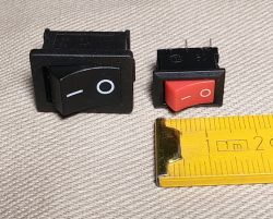
    The type of circuit breaker used by the Fellow has the drawback of a rather flimsy slider design.
    I suggest replacing the switch currently used with one from the photo below.
    This is the type commonly found in small domestic appliances.
    I am particularly mindful of the second one shown, due to its small size and red colour for ease of use.
    Black and red rocker switches and a yellow measuring tape on a light fabric background. .

    For the presentation itself I have the following question: where is the battery located?
  • #5 21129799
    TechEkspert
    Editor
    Very interesting analogue design, hearing aids used to be made like this at Omig, on germanium transistors:
    http://bee.mif.pg.gda.pl/Oktoda/index.php/AS-571
    https://a.allegroimg.com/s1024/0c44b3/18d71e9a4772b0b8b948573a334b

    In such constructions it is important that the limiter works and that too loud sound is suppressed,
    Ideally, there should be something like a compressor, which amplifies quiet sounds, lets loud sounds through, and muffles very loud sounds.

    Going deeper into the subject, hearing loss usually has a specific characteristic and, for example, we hear the bass better and the treble worse or vice versa,
    Therefore, such devices should also consider amplification in specific bands.

    Generally speaking, you can have your hearing tested for free in many audiological practices, and you will be given an audiogram which will show a separate chart for the left and right ear for each frequency. An audiogram will be available for both air and bone conduction, which can also be an indication of what works better.

    I used to make similar devices, I also added a limiter based on some AVT kit.

    Apart from such a device with a microphone, a compressor + band equalizer feeding the sound to a headphone and connected to the sound output of a radio or TV (leaving the sound in the speaker) works quite well. Then you can watch something on TV together without the volume control set to max....
  • #6 21129987
    yego666
    Level 33  
    You are right in the general case, and undoubtedly anyone wishing to make such a device on their own should take your advice into account for the benefit of the user of such a device.
    However, in this particular device, I have not implemented many interesting subsystems, such as a compressor or a fancy equalizer, because the obtained parameters of the device in its current shape are completely sufficient and meet the wishes of the user.

    As for the switch, it is exactly that, because it switches very lightly, and the user has rheumatic problems, so it is of great importance to him.

    The LiIon battery, on the other hand, is located under the PCB.
  • ADVERTISEMENT
  • #7 21129988
    TechEkspert
    Editor
    I checked out of curiosity and there is a free 'hearing test' app anyone can easily assess the state of their hearing organ.
  • #8 21130637
    kris8888
    Level 39  
    Why transistors Q5 and Q6 and not ordinary diodes in this location? Does this have any significant effect or influence on anything (on e.g. noise)?
  • #9 21130748
    yego666
    Level 33  
    In the first version I used 1N4148 diodes, which is what was recommended, but I noticed on the oscilloscope a waveform skip ( actually it was a saddle) when switching the output transistors.
    After replacing the diodes with transistors, this effect no longer occurs.
    I chose transistors so that they came from the same series, and had identical voltage drops at the B-E and B-C connectors, and since I have a whole bunch of them, I didn't have a problem with that. As a result, the sound is clear and doesn't have that pesky distortion.

    Surely someone proficient in the art could give the correct name for such distortion.
  • #10 21130756
    kris8888
    Level 39  
    yego666 wrote:
    Probably someone proficient in the art could give the correct name for such a distortion
    .
    Yes, this is crossover distortion. It's just that when you used diodes there was too little resting current for the terminal transistors. Apparently transistors Q5 and Q6 as diodes have a minimally higher conduction voltage than normal diodes which results in a slightly higher resting current, already offsetting this cross distortion.
    These transistors Q5 and Q6 do not have to be matched in a pair.
    If you were to replace Q5 and Q6 with a classic circuit with a potentiometer and a regulating transistor, you would be able to precisely set the resting current to the smallest possible value, but in such a way that no crosstalk distortion would occur.
  • #11 21130847
    yego666
    Level 33  
    Thanks for the expert explanation and definition. "Cross-cutting" - nice word :) .

    I did not pair transistors Q5 and Q6 but Q3 with Q5 and Q4 with Q6 to match the voltage drops across the connectors in such pairs.
  • #12 21130879
    kris8888
    Level 39  
    This is also unnecessary because all that matters is the sum of the voltage drops on Q5 and Q6. And in what proportions and whether they correspond exactly to the E-B voltage drops of transistors Q3 and Q4 is already irrelevant.

    You simply shot Q5 and Q6 in such a way that the sum of the voltage drops on them results in the rest current of transistors Q3 and Q4 on the borderline of crosstalk distortion.

    You would have achieved the same thing by selecting appropriate diodes in series or combinations of ordinary diodes and, for example, Shottky diodes.
  • #13 21130883
    LEDówki
    Level 43  
    Have you not thought about the TDA2822M? It will replace 5 transistors.
  • #14 21130894
    kris8888
    Level 39  
    LEDówki wrote:
    TDA2822M
    .
    It draws about 5mA of resting current at 3.7V supply. More than the author managed to wring out in this title project. And this, as I understand it, was also one of the design goals, i.e. to reduce the current consumption to a minimum.

    This is more likely to be something on an OP193. It draws extremely little resting current and can deliver sensible power to the handset.
  • ADVERTISEMENT
  • #15 21130913
    yego666
    Level 33  
    I considered various configurations and circuits, both integrated and less integrated.
    In the end, the spirit of the experimenter and a foolish belief in my abilities in a field in which I had no experience at all prevailed.
    Above that, I have several thousand unemployed transistors, so giving them a go is probably a Samaritan reflex on my part ;) .
    As you can see, the right starting point and a bit of reasoning + LTSpice produced a result that satisfies me and, more importantly, my Mum, for whom I made this circuit.
    The battery has a capacity of about 800mAh, so even if you forget to switch the device off, it will last for about a week without recharging.
    And then I'll plug it in and another week off :) .
  • #16 21130925
    LEDówki
    Level 43  
    The TDA2822 does not do resting current problems. Classical class AB power stages have current regulation and a transistor to maintain the correct voltage between the bases of the power transistors. I made a similar amplifier, but the gain lousy and high tendency to excite. The circuit is ready-made, from a kit. The power stage transistors are not polarised as here, and the gain is eliminated by magic feedback. Not really effective, although simple, as there are only 2 transistors added to the operational amplifier. BC109 is an old transistor. Perhaps a BC414 would be better?
  • #17 21130983
    acctr
    Level 38  
    If not a 2822/7050 then perhaps a ne5532 opamp plus a complementary AB power amplifier would suffice, all covered by the feedback. Minimal components, low noise and low resting current.
    Helpful post? Buy me a coffee.
  • #18 21131085
    yego666
    Level 33  
    I have noticed that there have been proposals for designs based on a variety of integrated circuits, but the proposals are so far very general.

    My problem - and I think a lot of people have a similar problem - was choosing a schematic that would be suitable for implementation.
    However, as we all know, the internet is all about viewership, hence people publish hundreds of different schematics that they have never built or tested, ergo you probably can't trust anyone unless you have at least a shadow of confidence in them.
    This was also the case with the schematic I relied on for this project.
    It contained errors that even someone as untrained as me was able to catch and correct, and in its original form it was unlikely to work well.

    The great value of forums such as Elektroda is that gradually people gain a certain reputation which allows others to place a degree of trust in such individuals and their projects.
    Such a reputation is not gained easily or quickly.
    The best way is to publish designs that have been tried and tested by hand, allowing others to replicate or improve such designs without risking failure.
    And this is probably the point of such forums.

    I therefore have a request to my esteemed colleagues to publish, in addition to free discussion, their proposals in the form of tried and tested designs where possible, in order to build both a base of trustworthy designs and their reputation.

    We will all benefit in this way and save time, which nobody has too much of.

    And to the System Administrator I would have this suggestion that, given the increasing number of elderly people who need support in various areas of functioning, some sort of competition should be held for various devices to help them with normal life.
    I am sure that many forum members would be very keen to use the designs created for this.
    I myself have already made quite a number of different devices for just such a purpose, and I can assure you that they are very much needed by our elderly relatives and friends, and what is more, they are very much appreciated.
    And what could be more valuable than the smile of a Father or Mother who is gaining lost opportunities through our goodwill?
  • #20 21132119
    yego666
    Level 33  
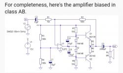
    The amplifier schematic looks logical and is uncomplicated, however, have you tested it?
    Furthermore, it seems to me by the output transistors that these headphones can have even a few watts of power, i.e. the amplifier is intended for the baaaaavery deaf audience :) .

    If the TL071 amplifier were used then we would gain the ability to correct the input offset and the second amplifier present in the TL072 would not be wasted.

    For me it would have been important to power the circuit from a small rechargeable battery so LiIon would have been perfect, whereas a 9V power supply probably requires a 6F22 battery or something similar, which is unlikely to be conducive to miniaturisation.
  • #21 21132278
    Mateusz_konstruktor
    Level 36  
    @yego666
    Turning an 8 ohm speaker into headphones and supplying a voltage much lower than specified in this schematic will result in much lower power.
    This was about presenting an idea.
  • #22 21132332
    yego666
    Level 33  
    Of course :) .
    You could also replace the output transistors with some BC547/557 or similar.
    The idea is of course worthy of emulation if one prefers such an arrangement.
    It is worth mentioning, however, that if we would like to go down with power supply to, e.g. 3V, TL07x will not be able to do it, because TI specifies power supply from 4.5V and ST from 6V upwards. So you have to use an amplifier suitable for such a supply.
    In the circuit shown above, the TL07x is OK because we have a 9V supply.
  • #23 21132359
    bratHanki
    Level 38  
    Miniature microphones can be obtained from old mobile phones.
  • #24 21132414
    acctr
    Level 38  
    yego666 wrote:
    The amplifier schematic looks logical and is uncomplicated, however have you tested it?
    .
    I haven't actually tested this schematic, but I've done similar circuits with the amplifier on mosfets and in class A.
    It's nothing complicated, an opamp takes care of a lot of things.
    The TL072 is used in audio because it is less noisy, but you can compromise and use the low power TL062.
    The opamp also lends itself well to a microphone preamp with possible band equalization.
    Certainly the circuit is easier to commission than a transistor-based amplifier
    Helpful post? Buy me a coffee.
  • #25 21132427
    Krzysztof Kamienski
    Level 43  
    yego666 wrote:
    that these headphones can have even a few watts of power, i.e. the amplifier is intended for baaaaavery deaf receivers .
    .
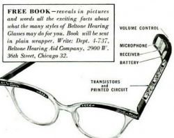
    For very deaf recipients, bone conduction electromagnetic transducers are used, not ordinary headphones. And for such transducers, firstly proper frequency correction is required, and secondly actually packing a few watts. And back in the 1950s, it was possible to fit an entire hearing aid into a spectacle frame.
    Photo of glasses with a built-in hearing aid from 1954, with components placed in the temples. Diagram of glasses with built-in Beltone hearing aid.
    So I rate this construction...average.
  • #26 21132643
    efi222
    Level 19  
    I view all amateur constructions positively. Each of them requires a commitment of time and effort. A colleague has built a device with which the user is satisfied. Even the PCB is made at home, which is increasingly rare.
    And as for operational amplifiers. In my opinion you can experiment with low voltage rail to rail amplifiers. E.g. LMV358. Power supply from 2.7V - 5V. I used one recently, as it was the 3.3V supply that was the critical condition.
  • #27 21132655
    acctr
    Level 38  
    efi222 wrote:
    low voltage rail-to-rail amplifiers. E.g. LMV358
    .
    It doesn't have to be r2r, low noise ICs are good to use in audio circuits and the 358 has never been that.
    Helpful post? Buy me a coffee.
  • #28 21133354
    yego666
    Level 33  
    Staying on topic, I would like to ask my colleagues about how to eliminate a certain unpleasant feature of such an amplifier.
    Like any device, the amplifier is housed in some sort of enclosure.
    In this case, I printed it out for myself on a printer.
    After inserting the device into the enclosure, it turned out that the microphone not only catches the desired sounds, but also those coming from unwanted sources such as knocks and thuds on the enclosure or those coming from rubbing against clothes while moving.

    In order to get rid of these unwanted sounds, I isolated the microphone from the casing using a thin sponge, then rubber, and finally, when it turned out that this did not help, I checked whether connecting a second identical microphone in a counter-phase would get rid of the problem.
    Of course, I isolated the second microphone with a low-density sponge from the source of the desired sounds.
    Unfortunately, the effect of such measures turned out to be very poor or even unnoticeable.
    In the end, I ran out of ideas and didn't want to reach for DSP in such a simple device.
    Do you have any simple patent for getting rid of such unwanted interference?
  • #29 21133371
    Krzysztof Kamienski
    Level 43  
    Using a differential microphone like in aviation headphones. Except that it's a bit expensive....
  • #30 21133398
    yego666
    Level 33  
    The MM217 costs around 60p, so it's still bearable, but the size is no longer acceptable in such a piece of equipment.
    I don't know how much such a microphone weighs, but it doesn't look light.

    Maybe someone has some other suggestions?

Topic summary

The discussion revolves around the construction of a custom acoustic amplifier designed for individuals with hearing difficulties. The author shares their experience in building the device, which utilizes a modified circuit based on the MAX9814 amplifier. Key improvements were made to address issues such as high resting current and noise, achieved through simulations in LTSpice. Participants suggest enhancements, including dual-channel configurations with two microphones and headphones for better sound localization, and the use of operational amplifiers like TL071 and TL072 for improved performance. Various components and configurations are discussed, including the use of transistors, diodes, and integrated circuits to optimize sound quality and reduce distortion. The conversation also touches on practical challenges, such as isolating the microphone from unwanted noise and the emotional impact of improved hearing on the user.
Summary generated by the language model.
ADVERTISEMENT