 .
.
I hope I don't bore you, with my next headphone amplifier. But somehow it just so happened that I've had the verve for such projects lately.
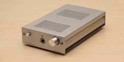
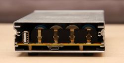
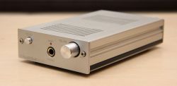
This headphone amplifier was created to be used with a phone or laptop. Hence my decision to power it from the built-in batteries (for easier and more versatile use), and to only equip it with a USB digital input.
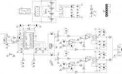
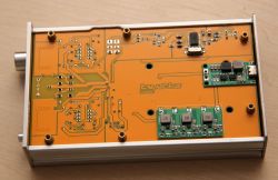
The schematic of my amplifier itself is overwhelmingly taken from the datasheet of the LME49600 chip. This chip is a very interesting buffer, ideally suited to the construction of such a device. It has been enhanced here with a USB DAC realised on the PCM2705 chip, which is easy to apply and works with various operating systems without problems. In addition, the amplifier has a battery charging circuit, as well as a cell balancing circuit. The latter two, are in the form of off-the-shelf modules. I made this decision mainly because these modules were already lying in a drawer, waiting to be used.
 .
.
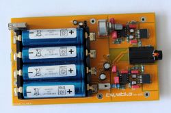
The circuits used, in terms of supply voltage, can work when powered by two cells connected in series. I, however, chose to power the device from a battery made up of four cells. And why did I choose these cells? Initially, I was thinking of using smaller sized cells, but as 18650 are probably the most popular, their price is more affordable than the smaller ones. Besides, on these, the amplifier can work for a really long time.
Before I go any further IMPORTANT NOTE for possible role models! .
The ground of the charging module, has a different potential than the ground of the amplifier circuit. They cannot be combined!
For this reason, an insulator has been glued into the charging connector hole located on the rear panel, in order to prevent accidental short-circuiting of the grounds when connecting the charger plug.
 .
.
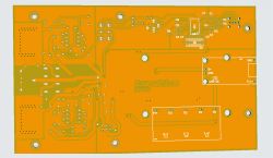
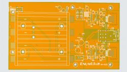
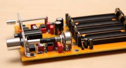
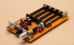
Back to my design. I have designed the following board:
 .
.
Which I commissioned from a company (I think) in a known part of the world.
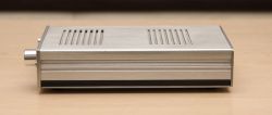
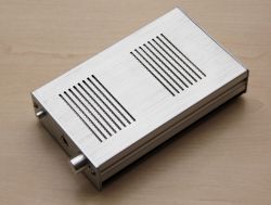
As for the casing. I think you will already recognise it in part. The main part of it is taken from one of my previous projects, which underwent a metamorphosis some time ago and received a new enclosure. So, these I have used here to make useful.
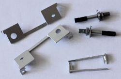
In completing the project on the mechanical side, a few more small components were needed. These include:
 .
.
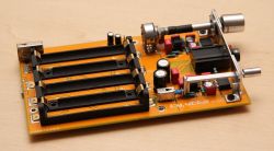
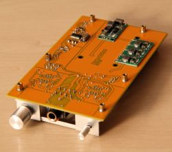
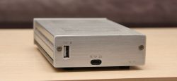
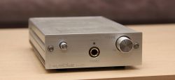
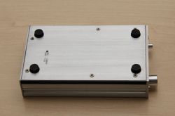
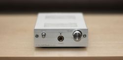
In order not to bore you with descriptions, hereafter just a few photos taken during the project.
 .
.
 .
.
 .
.
 .
.
 .
.
 .
.
 .
.
 .
.
 .
.
 .
.
 .
.
 .
.
 .
.
 .
.
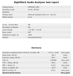
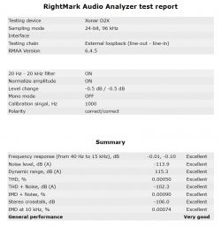
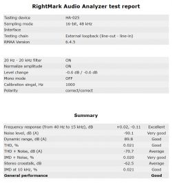
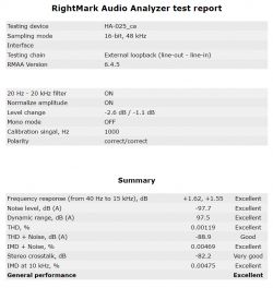
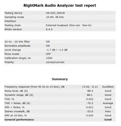
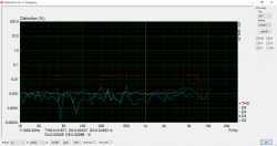
Below I still include the results of the tests carried out. Looks to the fact that, as in the design of my amplifier in the mains-powered version, the converter block from the PCM2705 affects the measured parameters in a negative way. i will still review this carefully.
 .
.
 .
.
Greetings and feel free to comment.
Cool? Ranking DIY


