How to build a rechargeable transformer soldering iron with TL494?
Hello.
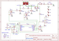
I used to really like the rechargeable soldering iron from this post: https://www.elektroda.pl/rtvforum/topic3303762.html and recently stated that I would attempt my own build. I already had all the parts recycled, the only thing missing was a flat bar for the secondary winding but this was found. The first prototype was according to the diagram from the link, but it didn't work very well, the zener diode (in my case a B-E transistor) got very hot and there was a lot of power loss. Well, but since I had a tl494 from an old ATX I figured I'd do it again only push-pull this time. It worked much better, the heatsink from the transistors is cold, the power is not missing.
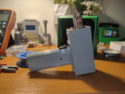
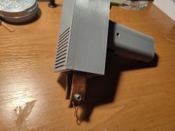
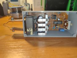
The operating frequency is 4Khz. The transformer is from an atx power supply and is probably ~1.2cm2 in cross section. The transformer generates its own power for the controller, the push-pull topology doubles the voltage on the primary side so it works great for us if the supply voltage is low. We have about 9-12V on the controller. The whole circuit requires at least 7V to start, below this something works, but the keys do not open fully and it is not able to generate a higher voltage to start. The trip threshold can be lowered by replacing silicon diodes with schottky diodes and/or transistors with a lower opening voltage. In theory the tl494 has undervoltage protection but something this piece of mine works even at <6V just produces some impaired waveform. But once it fires it works and even goes below 6V. There is a hole on the back of the case to adjust the power by changing the PWM fill. The blade is 0.75mm wire. The flat bar is 15x3mm, 12cm long. Because of the size and the material, the loss from conduction is negligibly small, but the loss from heat removal from the mainsail is already quite considerable and it heats up with continuous operation. If I were to make a second one, I would rather aim for an aluminium flat bar, I would make it longer and it would be even lighter and wouldn't pick up heat from the mainsail as much.
I made the winding from the kind of wire I had, the primary atx I think, a bit too thin but that's hard, it works. I measured twice 15 turns and at the output I have ~0.5V and all in all this is still too much, the mains only has 0.25V. And as you know twice the voltage requires 4 times less resistance to get the same power. So the blade needs to be quite thin, the one I have now is still a bit too thick and I need to have the power twisted. But too thin a blade will be too soft so it's not so easy to adjust. The problem with a heavy load(read thick/short arrowhead) is big voltage spikes on the transistors, up to 70V. For higher power you would need to improve the snubber network , you can add zeners to the transistors.
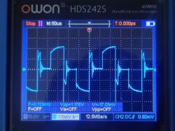
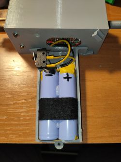
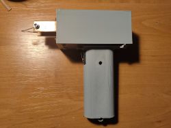
The current on the secondary is between 50 and 80A. The power supply is cells from a stripped Bosch hoover battery, they still have 1.8ah and a resistance of 35mR. The final weight is 300g. I still plan to add a power switch and a module to charge the battery when the stuff arrives from china. In the picture with the oscilloscope is the waveform on the flat iron at partial power. In the video he is testing the soldering iron at full power on a small heatsink.
 .
.
 .
.
.
I used to really like the rechargeable soldering iron from this post: https://www.elektroda.pl/rtvforum/topic3303762.html and recently stated that I would attempt my own build. I already had all the parts recycled, the only thing missing was a flat bar for the secondary winding but this was found. The first prototype was according to the diagram from the link, but it didn't work very well, the zener diode (in my case a B-E transistor) got very hot and there was a lot of power loss. Well, but since I had a tl494 from an old ATX I figured I'd do it again only push-pull this time. It worked much better, the heatsink from the transistors is cold, the power is not missing.
The operating frequency is 4Khz. The transformer is from an atx power supply and is probably ~1.2cm2 in cross section. The transformer generates its own power for the controller, the push-pull topology doubles the voltage on the primary side so it works great for us if the supply voltage is low. We have about 9-12V on the controller. The whole circuit requires at least 7V to start, below this something works, but the keys do not open fully and it is not able to generate a higher voltage to start. The trip threshold can be lowered by replacing silicon diodes with schottky diodes and/or transistors with a lower opening voltage. In theory the tl494 has undervoltage protection but something this piece of mine works even at <6V just produces some impaired waveform. But once it fires it works and even goes below 6V. There is a hole on the back of the case to adjust the power by changing the PWM fill. The blade is 0.75mm wire. The flat bar is 15x3mm, 12cm long. Because of the size and the material, the loss from conduction is negligibly small, but the loss from heat removal from the mainsail is already quite considerable and it heats up with continuous operation. If I were to make a second one, I would rather aim for an aluminium flat bar, I would make it longer and it would be even lighter and wouldn't pick up heat from the mainsail as much.
I made the winding from the kind of wire I had, the primary atx I think, a bit too thin but that's hard, it works. I measured twice 15 turns and at the output I have ~0.5V and all in all this is still too much, the mains only has 0.25V. And as you know twice the voltage requires 4 times less resistance to get the same power. So the blade needs to be quite thin, the one I have now is still a bit too thick and I need to have the power twisted. But too thin a blade will be too soft so it's not so easy to adjust. The problem with a heavy load(read thick/short arrowhead) is big voltage spikes on the transistors, up to 70V. For higher power you would need to improve the snubber network , you can add zeners to the transistors.
The current on the secondary is between 50 and 80A. The power supply is cells from a stripped Bosch hoover battery, they still have 1.8ah and a resistance of 35mR. The final weight is 300g. I still plan to add a power switch and a module to charge the battery when the stuff arrives from china. In the picture with the oscilloscope is the waveform on the flat iron at partial power. In the video he is testing the soldering iron at full power on a small heatsink.
 .
.


 .
.


Comments
I for one would probably end up in a psychiatric locked ward very quickly if I were to use your invention. I couldn't even manage to watch this short film without turning off the sound - the beeping immediately... [Read more]
Cool, I like the idea as well as the execution. Would it be worth to use here additionally some small uP to e.g. limit PWM filling automatically after heating the mainsail? [Read more]
How does the soldering iron perform with the thicker wire as a tip? . Do you hear any squeaks? [Read more]
The circuit squeaks in 4 kHz, you can definitely hear it, you would have to glue the transformer or something, but it doesn't bother me so far. To control the temperature of the mainsail, I don't even... [Read more]
Welcome, What is the purpose of this design? How is it better than a traditional transformer soldering iron? Indeed this squeak is hard to listen to. Regards [Read more]
. Such a design can be appreciated once you have used it a bit. I also once made something similar https://www.elektroda.pl/rtvforum/viewtopic.php?t=3785596&highlight= and it is still in use. It is... [Read more]
Hello Steel has several times the resistance compared to copper. The advantage is that iron does not dissolve in tin, so the blade will have a long life. With a precision current source of 5-20... [Read more]
Specifically, it is the resistivity. [Read more]
How did you measure the current on the secondary side? And how much power does it have realistically? I'm a bit confused why 4 kHz and not 25-30 kHz, so that at least it doesn't squeal so cruelly. [Read more]
Idea good, execution so-so. Definitely needs fine-tuning and getting rid of the squeak. [Read more]
. On the secondary side, the current is measured by measuring on the primary side and multiplying by 15. A 4KHz because to reduce the skin effect on the flat. [Read more]
At 4 kHz the penetration is at 1 mm... for 20 kHz 0.46 mm Like replacing the flat bar with sheet metal it would work better and wind up easier.... The secondary current is not 15 times the primary... [Read more]
Eastern DIYers also had ideas for an electronically controlled induction soldering iron. This is one such article: Autonomous DIY mini induction soldering iron. . An induction soldering... [Read more]
. At 25 kHz you have to reduce the number of turns on the primary, and on the secondary you can no longer do that and the voltage will be too high. [Read more]
Thanks for sharing the build, as I understand it is a soldering iron for field work? :) . Send me a Parcel Post on Private Message and I will send a small gift. [Read more]
You take your time to mute the inverter. Rodents leave areas where sounds above 3 kHz are propagated. You have a mouse deterrent right away. You run it in autumn and there will be fewer rodents in the... [Read more]
. I continue with your joke: Too simple to complicate! The dream of many. How to repair with such a soldering iron in the field? Something sparks, sometimes squeaks.... Some solder not making... [Read more]
On aliexpress you can buy very good soldering irons for T12 arrowheads with usb-c socket for up to £ 100. Add to this a powerbank with PD 3.0 support for 20 volts and you have a ready mobile kit. It only... [Read more]
This is your opinion. I have been using the soldering iron as in the topic for years on some occasions and it sometimes beats the T12 (I have that three) so don't sow ferment. Soldering is not an end in... [Read more]