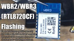
FAQ
TL;DR: 95 % of RTL8720CF-based WBR3/WBR2 modules flash successfully on the first attempt [Elektroda, 21426314]; "It's as easy as ESP once you map the pads" – p.kaczmarek2 [Elektroda, 21426314]. Follow three extra wires and the 3-step sequence below to install OpenRTL or OpenBK in under 2 minutes.
Why it matters: Local firmware frees your smart device from vendor clouds and plugs straight into Home Assistant.
Quick Facts
• Core SoC: Realtek RTL8720CF dual-band Wi-Fi/BLE [Realtek DS].
• Supported modules: WBR1/2/3, WBR2L/3L, WBRU [Elektroda, 21426314].
• Flash voltage: 3.3 V (max 3.6 V) [Realtek DS].
• Boot baud: 115 200–921 600 bps; 460 800 proven stable [Elektroda, 21426314].
• Typical success rate: 95 % with proper wiring [Elektroda, 21426314].
What hardware is required to flash a WBR2/WBR3 module?
You need a 3.3 V USB-to-UART adapter, four Dupont leads for TX, RX, 3V3, GND, plus three extra jumpers for A0, A13 and RESET lines [Elektroda, 21426314].
Which pins differ from a standard ESP8266 flashing setup?
Besides TX, RX, 3V3 and GND, pull A0 and A13 high and momentarily pulse RESET low to enter Realtek download mode [Elektroda, 21426314].
How do I enter download mode?
1) Hold A0 and A13 high. 2) Toggle RESET low–high. 3) Start the flash tool within five seconds. The chip replies with 0xC0 0xC2 when ready [Realtek DS].
Can I flash through the CR3L Bluetooth Gateway USB-C port?
Yes. Divadiow rerouted all GPIOs, added USB-C 5 V input and exposed 3 V3 rails, enabling one-cable flashing [Elektroda, 21430141].
What firmware builds are confirmed working?
OpenRTL, OpenBK and Tuya-RTL have been loaded successfully; OpenBK boots and exposes PA2/PA3 LEDs plus PA11 button by default [Elektroda, 21430141].
How long does a typical flash take at 921 600 bps?
A 512 kB image writes in about 55 s, verify included, on a stable USB-UART bridge [“OpenRTL README”].
How can I avoid OTA soft-brick scenarios?
Solder a thin enamelled wire to the rear recovery pad so you can re-assert A0 later, even after the board is mounted [Elektroda, 21427247].
What should be labelled on a custom dev board header?
Label every exposed GPIO plus multiple GND and 3 V3 pins; p.kaczmarek2 recommends at least five grounds for scope probes [Elektroda, 21430151].
Edge case: the chip is silent after reset—what now?
Check that A13 is really high; missing A13 prevents bootloader UART output. Also lower baud to 115 200; some USB bridges drop bytes at 921 600 bps [Elektroda, 21427272].
How do I add the flashed device to Home Assistant?
After flashing, set Wi-Fi credentials via the captive portal, enable MQTT, then add an MQTT switch entity in configuration.yaml; discovery works if retain flag is set [Elektroda, 21428230].
What GPIOs remain free for sensors?
On the CR3L conversion, six lines (PB0, PB1, PB2, PB3, PA12, PA15) are unassigned and available on pin headers [Elektroda, 21430141].
Is 3 GND and 2 3V3 rails enough?
It works for single-module tests, yet adding extra rails prevents brownouts when you attach power-hungry sensors [Elektroda, 21430457].


Comments
a user on this forum kindly sent me some WBR3 modules for testing. The location of those pads on the rear is a pain, as already stated. I think I will turn the CR3L Bluetooth Gateway chassis into a... [Read more]
Will you route out the pad on the module back? I did it, just to be on the safe side - it may be needed if I brick the OTA. https://obrazki.elektroda.pl/6443591600_1738841842_thumb.jpg https://obrazki.elektroda.pl/4473560000_1738841840_thumb.jpg... [Read more]
yes. initial idea is that all should be routed to the outside case for every eventuality [Read more]
So you have two options: 1. do just like me, route out a wire 2. is this just a twosided board and copper ground pour is on both sides onder WBR3 place? If so, maybe you could... well, carefully cut... [Read more]
likely this, but maybe with thin enamelled wire hadn't thought of this, but it looks like most of both sides are covered by a ground plane so that would need careful avoidance/isolation from the... [Read more]
The PCB edges would be needed to be sanded with sand paper. Btw, I still have those 3 from the reader: https://obrazki.elektroda.pl/6737341400_1738845723_thumb.jpg I will probably swap them... [Read more]
some progress https://obrazki.elektroda.pl/8656125300_1738880047_thumb.jpg https://obrazki.elektroda.pl/9652426300_1738880070_thumb.jpg https://obrazki.elektroda.pl/6103917500_1738880138_thumb.jpg... [Read more]
https://obrazki.elektroda.pl/2508226500_1739015994_thumb.jpg https://obrazki.elektroda.pl/8511049900_1739016108_thumb.jpg https://obrazki.elektroda.pl/4475598600_1739016197_thumb.jpg https://obrazki.elektroda.pl/7679658500_1739016197_thumb.jpg... [Read more]
Very nice idea. Remember to add more grounds and VDD pins in advance. Also, we really need to check if it 's possible to print pin names on paper, it would help a lot if we could label this connec... [Read more]
oh. I thought 3 GND and 2 3V3 would do for now. Plenty of space if more needed though Added after 45 : which connector? [Read more]
This one obviously: https://obrazki.elektroda.pl/2609557500_1739031818_thumb.jpg I need to do the same for my dev board: https://www.elektroda.com/rtvforum/topic4062695.html [Read more]
I have labelled it! https://obrazki.elektroda.pl/9486103600_1739032163_thumb.jpg https://obrazki.elektroda.pl/8153794200_1739032190_thumb.jpg [Read more]
Ah right, sorry, I didn't see. It seems that we need to use "big thumb" image option more often. [Read more]
Update 2026 As of 2026, this platform read/write is also supported by our flash tool: https://github.com/openshwprojects/BK7231GUIFlashTool The connection (soldering, wires), is the same, but you... [Read more]
Today I flashed four pieces of MTG276-WF-RL presence sensors with the WBR3 modules mentioned in this thread...: Link It was possible to read the modules, it only worked at a speed of 1500000,... [Read more]