LN882H TNCE RGBCW WiFi LED bulb - LN882HKI flashing tutorial, UART to USB, pinout
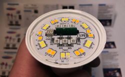
Here's step by step guide for the LN882 (LN882HKI by Lightning Semi) TY-BK-A60 LED bulb firmware change. This will let you to run the device cloud free and pair with Home Assistant. Device will be flashed with our Tasmota/Esphome inspired firmare, OpenLN882H. A simple USB to UART converted will be used for that. The programming process shown here will be fairly simple and will not require full bulb disassembly. The bulb was bought on Ali for few $, it can be sometimes even bought for as low as 1$. Let's look at the packaging:
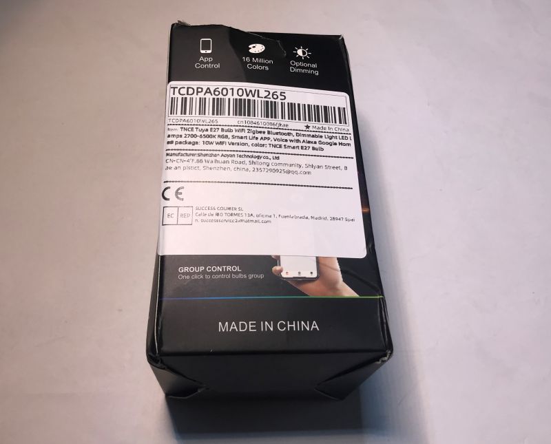
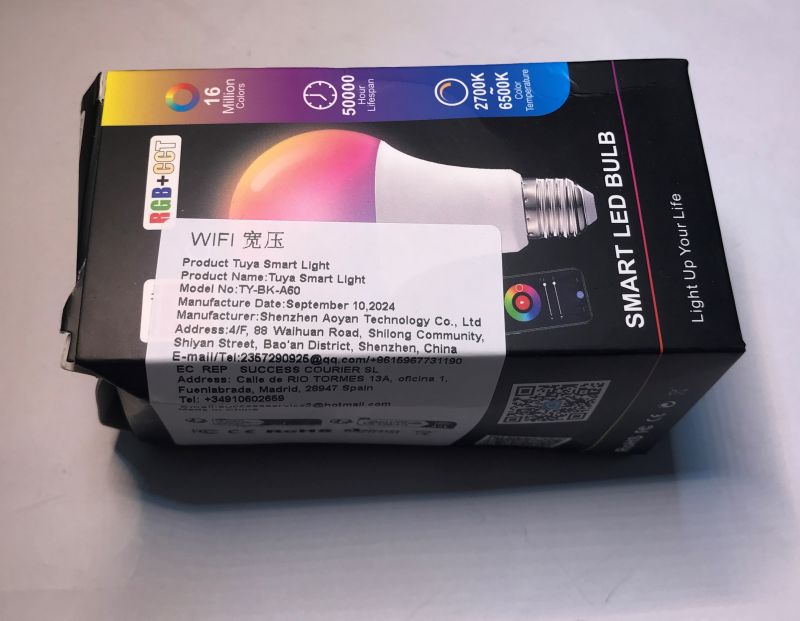
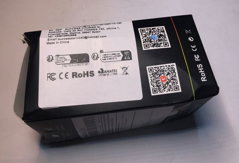
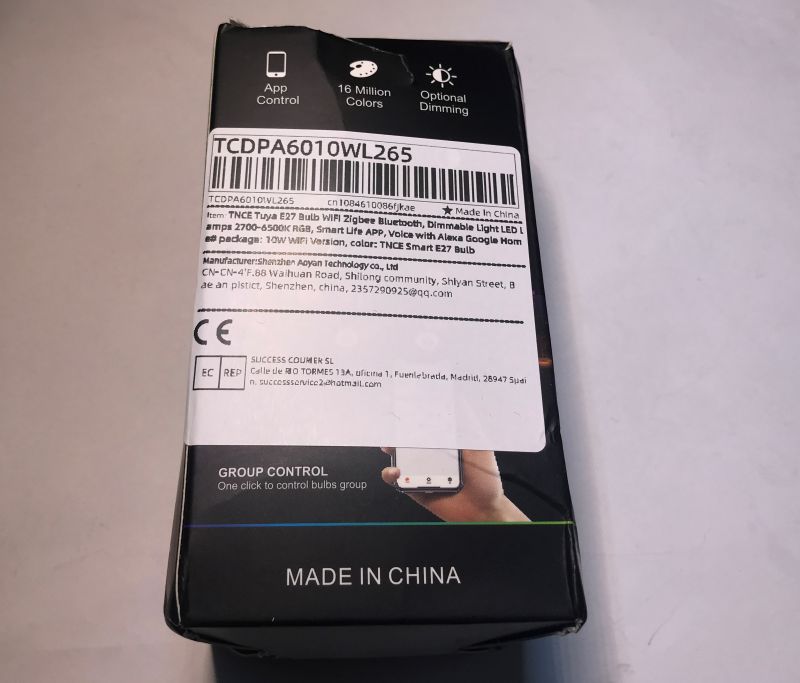
TNCE Smart E27 Bulb - TCDPA601WL265
Model: TY-BK-A60
Manufactured: September 10, 2024
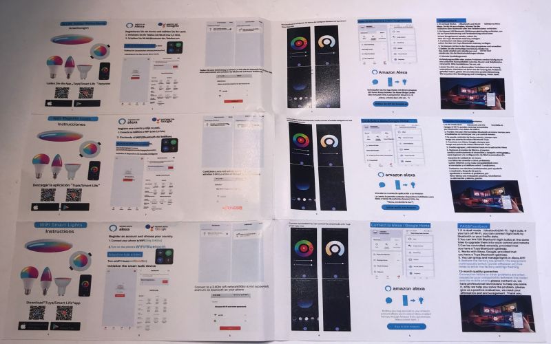
There is also a manual inside, but we don't need it as we're going to change the firmware:
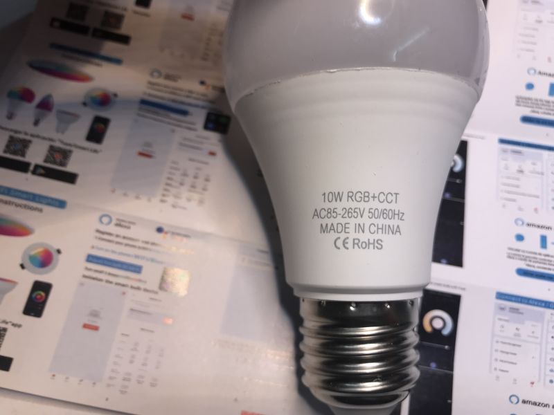
and the bulb itself:
Bulb teardown
Top dome can be easily removed with some force. I managed to do it with my bare hands:
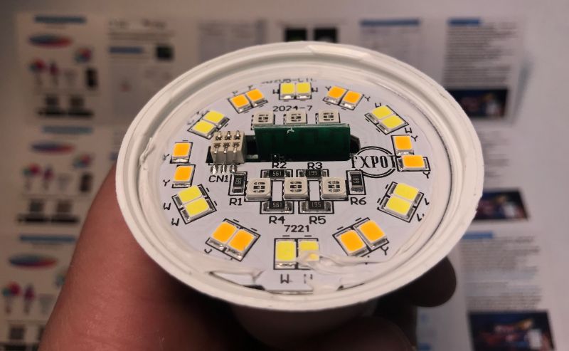
Then I had to remove the LED board. I had to pry it with screw driver, it was a bit problematic. I broke the part of the bulb edge:
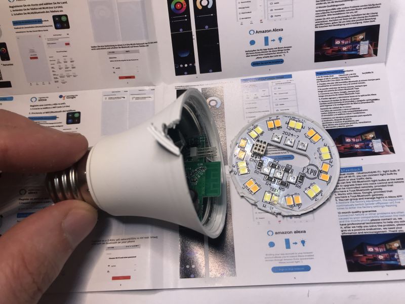
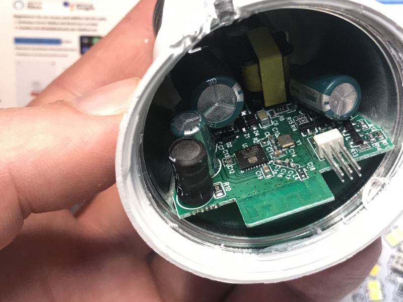
Finally, as you can see, we're getting access to the WiFi MCU:
It's not a Beken chip this time, but a LN882H:
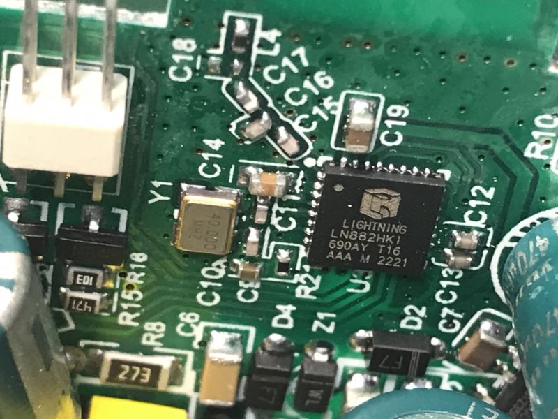
LIGHTNING LN882HKI, to be precise.
You can also see five transistors nearby, so probably bulb uses raw PWMs. No I2C LED controller there.
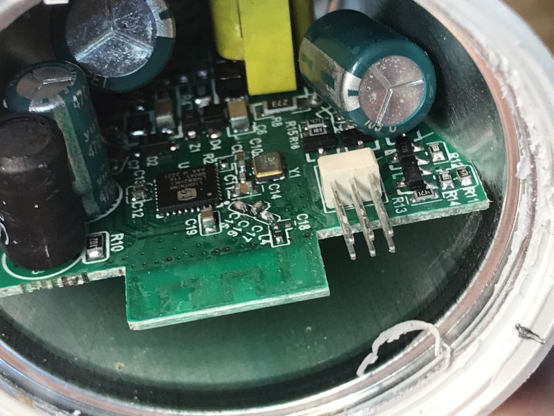
It is also possible to glance at the power supply circuit in the back:
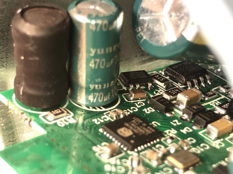
It's a step down converter based on BP2525, just like usual. It's a very common solution in these products.
I can also see a KP2120 (KP2120SG?) in the background, so the LED circuit might have a separate supply than a WiFi SoC.
There are also flashing pads on the bottom of the board:
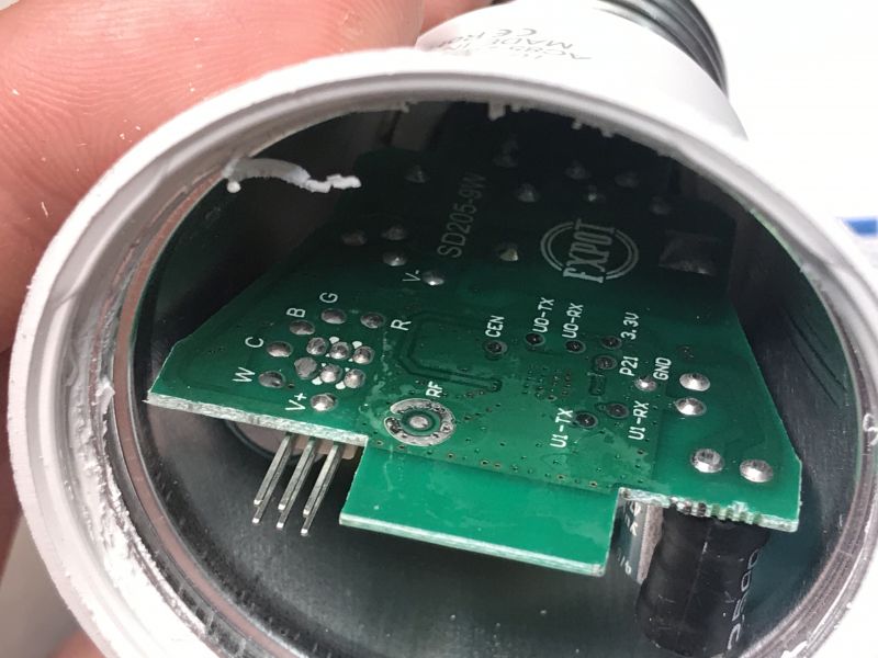
P21 may sounds like a Beken pin. I think it's a left over from previous device version which might have used BK7231.
Firmware change
P21 is actually a LN882H boot pin. The programming UART is in the background, U0-TX and U0-RX. First add some flux and Pb solder to the pads:
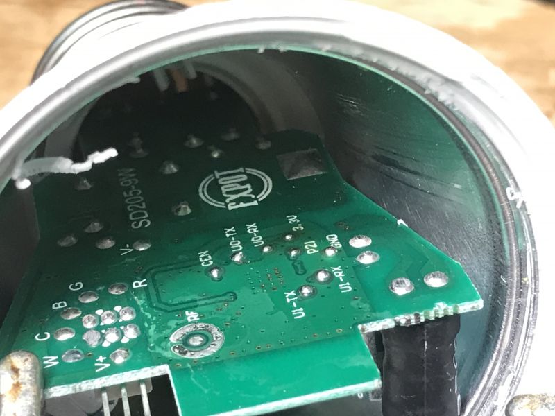
Then solder wires:
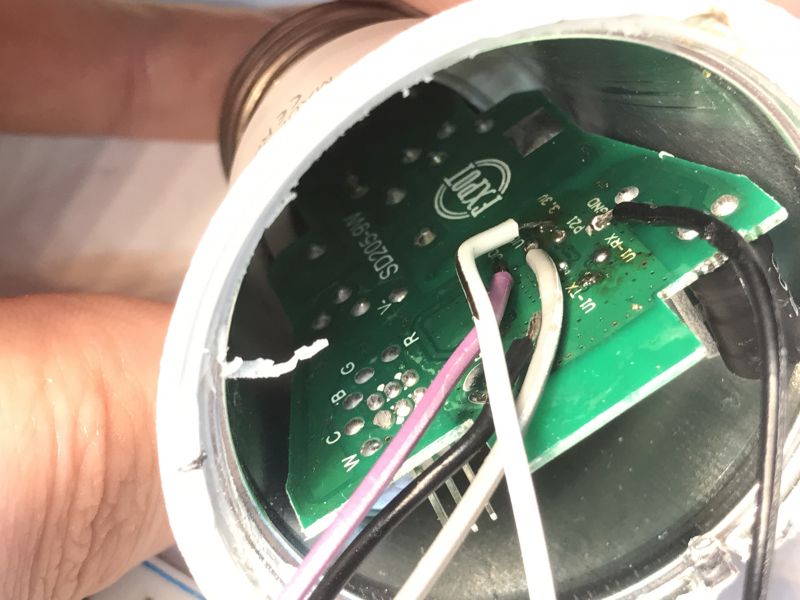
Follow LN882H flashing tutorial:
https://www.elektroda.com/rtvforum/topic4028087.html
https://www.elektroda.pl/rtvforum/topic4028087.html
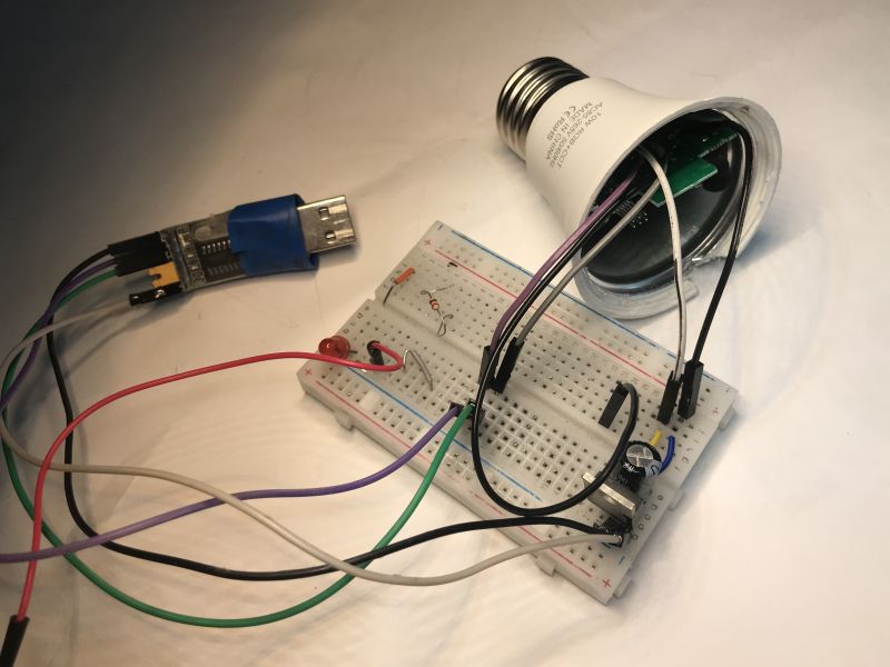
Here's my full circuit:
Of course, I've also took a backup of original firmware first. It's not full 2MB because I had to interrupt read early, but it seems that data past 1MB mark is just full of 0xFF:
https://github.com/openshwprojects/FlashDumps/commit/5e7d1bf6dac8c79dc68b34dfd6e781d435bfce42
Initial setup
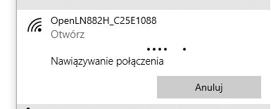
Just like with Tasmota - disconnect boot pin, do power off/on, connect to LN822H access point:
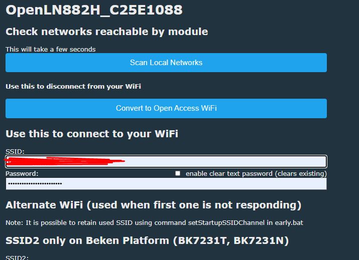
Configure your WiFi:
Get new device IP from DHCP:
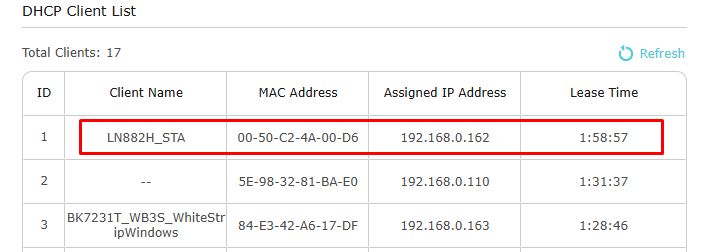
Then you need to figure out the GPIO roles. We don't have yet GPIO extraction for this platform, so I used the GPIO Doctor tool from the Web App.
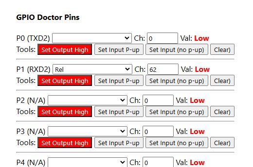
Once you guess the pins with Doctor, you can set them to PWMs in Configure Module menu:
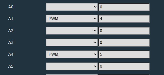
At first I got CW working:
This is how CW controls look like:
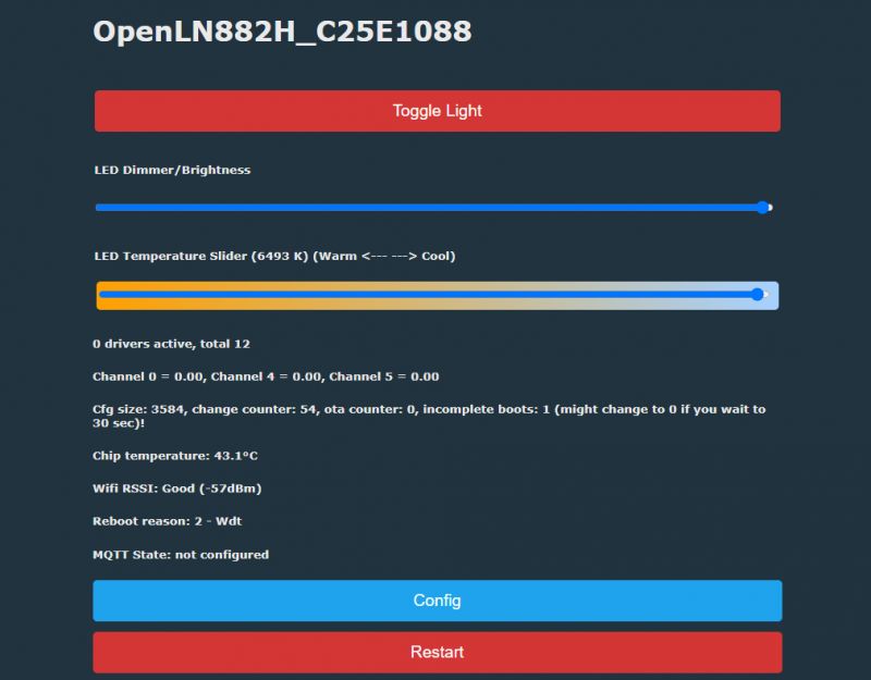
CW seems to work good:
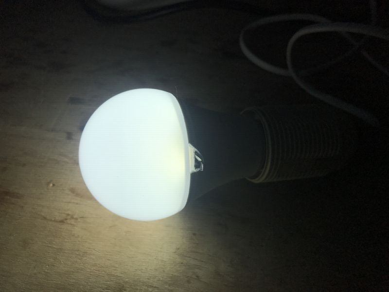
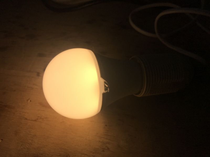
Later I found RGB pins, so RGBCW is fully working now.
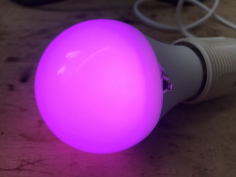
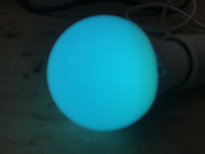
RGBCW configuration:
Code: JSON
Summary
Flashing process was easy and didn't require full disassembly of the bulb. I have managed to reach the pads with my soldering iron and I didn't have to remove the thread. I also guessed the meaning of pad markings - U0 is used for flashing and P21 is infact the LN882 boot pin. I also managed to guess the GPIO roles with GPIO Doctor, so full RGBCW is working now.
Device can be now paired with Home Assistant, just like in our tutorial.
Let us know if you have also encountered any LN882H devices already. We can help you with flashing and HA setup.
PS: Special thanks to @divadiow for helping me to get this bulb. I've ordered another already, this time E14 thread, we will see if it will be also LN-based...


Comments
And would it go via OTA, Tuya-convert + tasmot? [Read more]
Unfortunately no. It only goes on devices with ESP and, in addition, most new devices are protected. The LN882HKI is a completely different MCU. We specifically wrote HAL for it to port firmware to... [Read more]
Thanks for the reply. I haven't tried flashing yet, for now I'm gathering info:) I have a couple of these toys, but they are in daily use. Just planning to buy something to play with, with different BK... [Read more]
Well, two comments I have. First, you're not sure if you're going to get something on LN882H, or BK7231, or BL602, or W800, so don't assume that in advance. But anyway, OpenBK/OpenLN supports most of... [Read more]
Well, yes, that's true. I don't have the certainty. Once I have something to play with, I'll only wonder. And I will report back on the successes:) . [Read more]
I've just ordered more leds myself for testing, we'll see what arrives: https://obrazki.elektroda.pl/3546375900_1740167568_bigthumb.jpg . I am now awaiting the three packs: https://obrazki.elektroda.pl/2792321000_1740167735_bigthumb.jpg... [Read more]
A package has arrived with this one: https://obrazki.elektroda.pl/2251816100_1740521229_bigthumb.jpg . It turned out to be based on the BL602 - BW2L module . I am working on it. It is possible to... [Read more]
It came with: https://obrazki.elektroda.pl/5068268800_1740612311_bigthumb.jpg . CB2L. https://obrazki.elektroda.pl/4723763000_1740612445_thumb.jpg . Added after 10 [minutes]: . Ordering... [Read more]
I ordered, also, a zigbee version of the bulb. There is a BZ2L module inside with a BL702 microcontroller. The bulb is an Ewelink SMART A60 https://obrazki.elektroda.pl/2380516700_1740729328_thumb.jpg... [Read more]
Zigbee it will run right away, no need to flash, but as if you want to experiment it is also possible to dump and upload the memory: How to read and back up the flash memory of a BL602/BL702/etc device... [Read more]
I flashed this (18W version): https://obrazki.elektroda.pl/8009960700_1740829539_bigthumb.jpg . Unfortunately the CB2L programming pad is on the bottom. I had to solder it out. Problematic copy. I... [Read more]
The E14 led mentioned earlier in this topic from eWeLink turned out to use BL602. Today I also ordered an E14, but not from eWeLink, but from Tuya, to see if it would also be a BL602 or perhaps further... [Read more]
. Received - 2025.03.06 There is an LN882H with BP5758 inside (not PWM!). KA0600152-ibbd [Read more]
Assuming eWeLink-C3009-EW-E14-BWL2-bulb-20250225.bin is from this bulb: Starting bl602 now.... ############################## system init ################################## Device Info:[Firmware... [Read more]
@divadiow the Matter bulb also arrived: https://obrazki.elektroda.pl/7579101400_1741294191_thumb.jpg https://obrazki.elektroda.pl/9937662100_1741294193_thumb.jpg https://obrazki.elektroda.pl/2242260200_1741294193_thumb.jpg... [Read more]
ooh. I hope it isn't too, but I have a small pile of ESP Matter devices that are :( [Read more]
Do you know the debug log output baud rate for this module? [Read more]
74880? [Read more]
Normal mode: ESP-ROM:esp8684-api2-20220127 Build:Jan 27 2022 rst:0x1 (POWERON),boot:0xc (SPI_FAST_FLASH_BOOT) SPIWP:0xee mode:DIO, clock div:1 Valid... [Read more]