Another Smart Switch easy to run locally with Home Assistant - ATLO-B1-Tuya
 .
.
Here are the firmware change instructions for another budget WiFi controlled relay. The product presented here normally works with the Tuya cloud, but here I will show how it can be freed from the cloud and paired with Home Assistant. The unit discussed here appears under the ATLO-B1-Tuya model and already belongs to the newer series of Smart Switches, as it uses the BK7231N. The gadget itself is available to buy in two versions - a version with energy measurement (based on the BL0937), and a regular version, here I will show the latter.
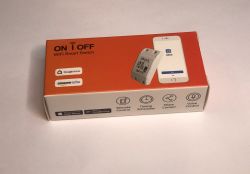
Let's start with the packaging, the unit shown here I had from a reader, I changed the firmware for him on request throughout the set of devices.
 .
.
 .
.
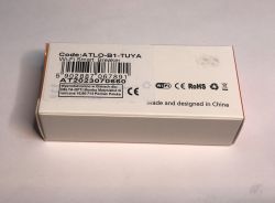
You can see that the equipment was bought in our country, probably for a few tens of zlotys, although it would have been cheaper from China.
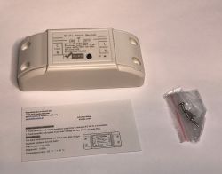
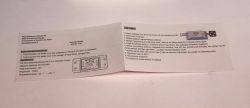
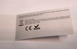
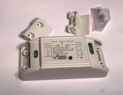
Contents - they even gave screws for fixing:
 .
.
 .
.
 .
.
Test with Tuya I skip, it's time to look inside and change the firmware.
 .
.
 .
.
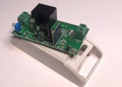
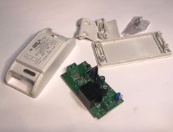
Inside sits a relay that only cuts off one wire - assumed to be a phase, but you know, it depends how you connect. Apart from that, we have a non-isolated power supply (step down) and a 3.3V LDO regulator and WiFi module.
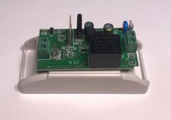 .
.
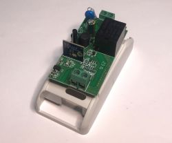 .
.
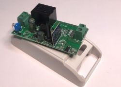 .
.
The input to the inverter is protected by an F1 fuse, next to this we also have a varistor, and then an incomplete filter (the chokes are omitted - e.g. L3 is missing). In the plans there was also a fuse F2, the one from the phase going to the device, but it was omitted.
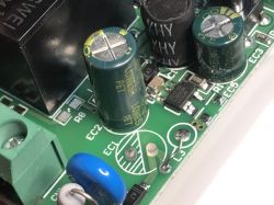 .
.
The step-down converter itself (which converts these rectified 230V to 5V for the relay) is based on a BP2525. Separately further down we have the AMS1117-3.3V.
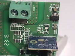 .
.
There is still room on the board for the aforementioned BL0937 along with a resistor/bypass for current measurement.
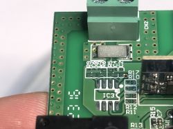 .
.
You can also see the bold current paths from 230V:
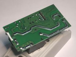 .
.
The firmware change is done according to the instructions of our flasher:
https://github.com/openshwprojects/BK7231GUIFlashTool
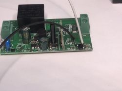
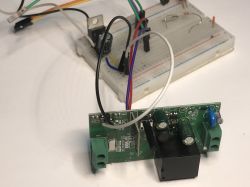
We prepare a USB to UART converter as standard, on the other hand we don't need a 3.3V power supply/stabiliser as you can feed 5V to the input of the one on the board:
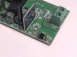 .
.
 .
.
You can't feed 5V into the CB2S power supply, because then you will damage it.
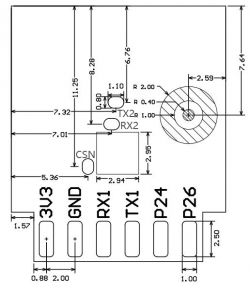
We also need to add wires to the RX1 and TX1 pads from CB2S:
 .
.
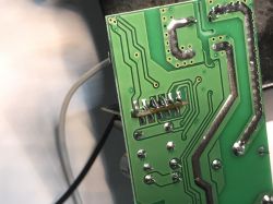
I first apply flux, then add a bit of lead binder and solder the previously whitened wires too.
 .
.
 .
.
If you have any problems, you can take a look at our Electrode playlist and watch videos about the BK7231 there:
https://www.youtube.com/playlist?list=PLzbXEc2ebpH0CZDbczAXT94BuSGrd_GoM
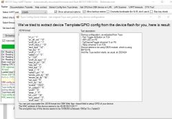
Plug everything in, start the flash read in the flasher and do a power cycle, i.e. disconnect and connect the 5V power cable. The flasher should read the batch including the configuration:
 .
.
JSON Tuya:
Code: JSON
OBK template:
Code: JSON
GPIO verbal description:
Device seems to be using CB2S module, which is BK7231N chip.
- Relay (channel 1) on P26
- WiFi LED on P8
- TglChannelToggle (channel 1) on P6
- Pair/Toggle All Pin on P24
Instructions for uploading the template:
Instructions for pairing with HA:
Operation successful - patient disconnected from the cloud. Can work with HA as well as being freely scripted, configured and even able to handle additional sensors, buttons and relays. Details on Github of the project . You can also take a look at our list of device templates and on Youtube Elektrodam.com .
If you have any questions, I'm happy to help - the firmware presented here also supports other, less popular chips, so even if your switch is not based on BK, it's still probably possible to change the firmware.


Comments
Hi, I have one of these, and I tried to follow this guide. It looked like everything went fine, the flasher reports "success" at every step. However now the unit powers up, the led glows blue, but quite... [Read more]
One more thing: this is the data I got from the flasher when backing up the original firmware: { "rl1_lv":"1", "on_off_cnt":"10", "onoff_rst_m":"1", "onoff_clear_t":"10", "rand_dpid":"42", "net_trig":"4", "onoff_n":"3", "netled1_lv":"0", "jv":"102", "onoff_rst_type":"2", "total_bt_pin":"24", "nety_led":"2", "total_stat":"2", "reset_t":"5", "netled1_pin":"8", "remote_add_dp":"49", "remote_list_dp":"50", "net_type":"0", "inch_dp":"44", "module":"CB2S", "ch_cddpid1":"9", "onoff1":"6", "clean_t":"5", "init_conf":"38", "zero_select":"0", "onoff_type":"0", "series_ctrl":"0", "total_bt_lv":"0", "cyc_dpid":"43", "remote_select":"0", "ch_num":"1", "rl1_pin":"26", "netn_led":"2", "ch_dpid1":"1", "crc":"20" } ... [Read more]
Thanks for sharing, I appreciate you. [Read more]