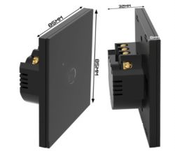
I will present here the process of changing the firmware of another product popular on the Polish auction site, this time the WiFi-controlled light switch model SmartLED 8044. The purpose of changing the firmware will be to free it from the cloud and pair it with Home Assistant, this time 100% locally. I will put here the full GPIO template of this device generated by my flasher based on the Tuya configuration partition.
Product purchase
The product was bought in several pieces by one of our forum members, for whom I only changed the firmware in this switch (actually: in the switches, because I got some to rework) the firmware, so that he could connect them locally with HA. Thank you for sharing your play equipment. Below is a screenshot of the auction:
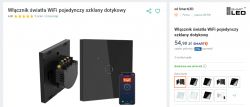
PLN 54 is a good price for a product that we can get with free shipping (in the right package) within 2 days, even at a parcel locker. We also have a choice of color here, as well as a similar version with 2 or 3 buttons.
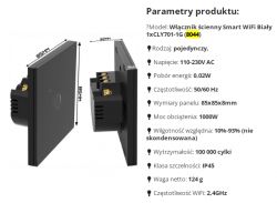
The model name is 1xCLY701-1G or 8044.
parameters:
Let's see what we get in the kit:
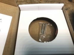
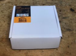
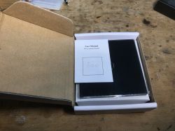
there are screws for mounting - and the switch:
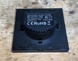
Interior 8044
I skip the tests with the Tuya application - this has been discussed on the forum many times. I will only briefly present the interior and then show the specific procedure for changing the firmware and the GPIO template.
We undermine the front:
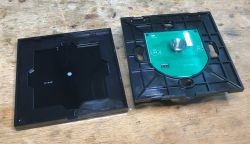
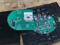
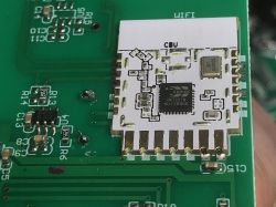
Inside there is a CBU - a module based on the BT/WiFi BK7231N chip:
Here is its specification:
https://developer.tuya.com/en/docs/iot/cbu-module-datasheet?id=Ka07pykl5dk4u
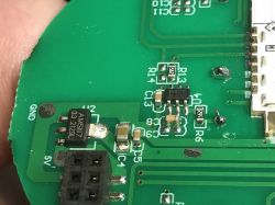
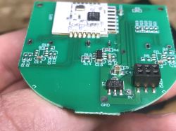
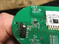
On the board I also see AMS1117-3.3V, which converts 5V to 3.3V for the WiFi module, and a touch button controller, RH6016C.
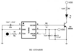
You can also see places for two more circuits for the other two touch buttons.
Here is the CBU itself, even without looking at the Tuya documentation, you can guess where the power is, you can see the 100nF SMD decoupling capacitor:
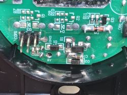
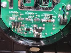
And a glance at the power supply - we have a BP2525 power supply here again. The photo also shows one of the three relay transistors, SMD code J3Y.
Firmware change
We're playing OpenBeken , it will provide us with a Tasmota-style experience and compatibility with its ecosystem (to some extent), compatibility with its JSON format, some commands, and with the Tasmota Device Groups system. We flash with the flasher, through the converter to USB and UART, according to the readme:
https://github.com/openshwprojects/BK7231GUIFlashTool
CBU pinout we have here:
https://developer.tuya.com/en/docs/iot/cbu-module-datasheet?id=Ka07pykl5dk4u
In addition, I made a graphic showing what and how to connect:
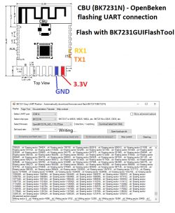
This flasher can download the latest OBK release by itself. We just solder 3.3V, GND, RX and TX, perform a power cycle and wait for the end of the upload.
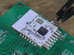
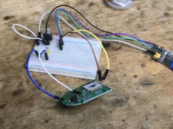
There is no philosophy here, no blocked RX/TX line, no TuyaMCU, no need to desolder anything, no problems.
I got the configuration like this:
Template:
Code: JSON
Summary
Changing the firmware here was seamless. You just have to do four February and off you go. The product is relatively cheap (as for our Polish market - the distributor also has to earn money), fast delivery (for parcel lockers), nothing to complain about. After uploading the OBK, you can read the tutorials from our Elektroda.com channel:
https://www.youtube.com/@elektrodacom
I would like to add that I recently removed the configuration of Tuya devices with my flasher, which also speeds up the work. I already linked the details in the thread.
A reader gave me some of these switches to be processed, also in a triple and double version, so if something surprises me inside them, I will soon complete the topic or place a separate topic about its related version (probably the 8046 model).
Cool? Ranking DIY Helpful post? Buy me a coffee.


