SMD learning kit/kit - LED shell animation - NE555 and CD4017
 .
.
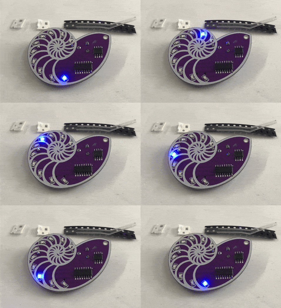
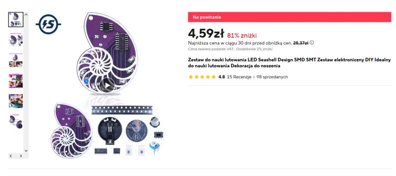
Here I will present a self-assembly kit based on SMD, or surface mount, components. This simple kit allows you to practice soldering circuits in enclosures such as SOP-8, SOP-16 and 0805. Once assembled, you get a simple "flowing light" effect. The whole thing can be bought for around £25, although you can get it for up to five times less in a promotion.
 .
.
The kit presented here is for anyone who wants to practice soldering surface-mount components. There are various ways to solder it - you can even solder it in a suitable oven, but I solder it "on foot" with the - cheapest soldering iron, flux, binder, tweezers.
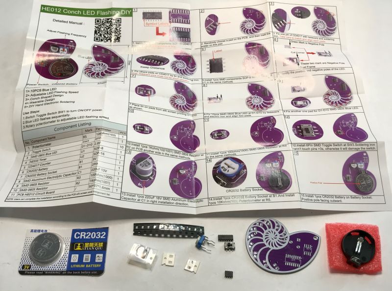
Let's start with the contents of the kit. In addition to the board and the required parts, we also get an easy-to-understand English-language manual with pictures:
 .
.
Already at this stage I can see that we got spare resistors (two each instead of one) and with two spare LEDs. That's good, they're easy to lose.
There's a CR2032 battery too, for power.
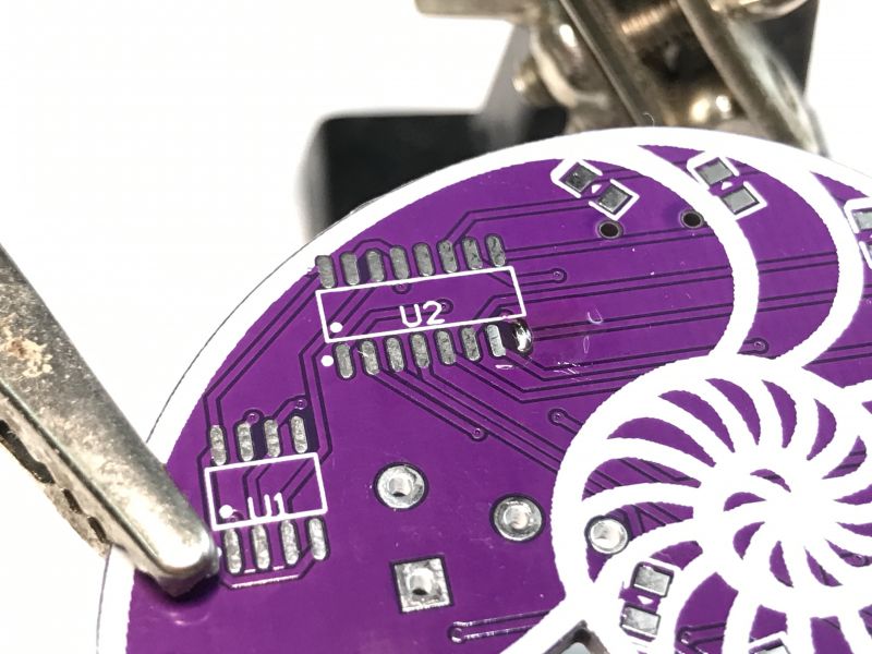
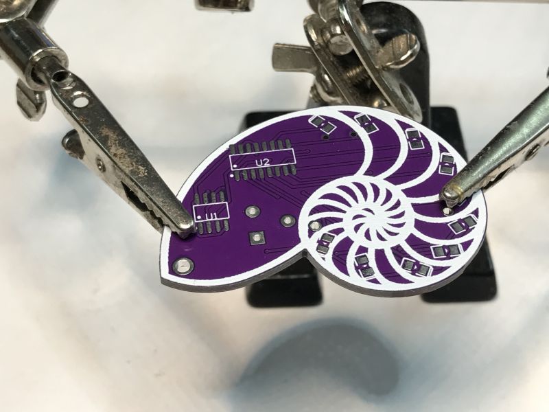
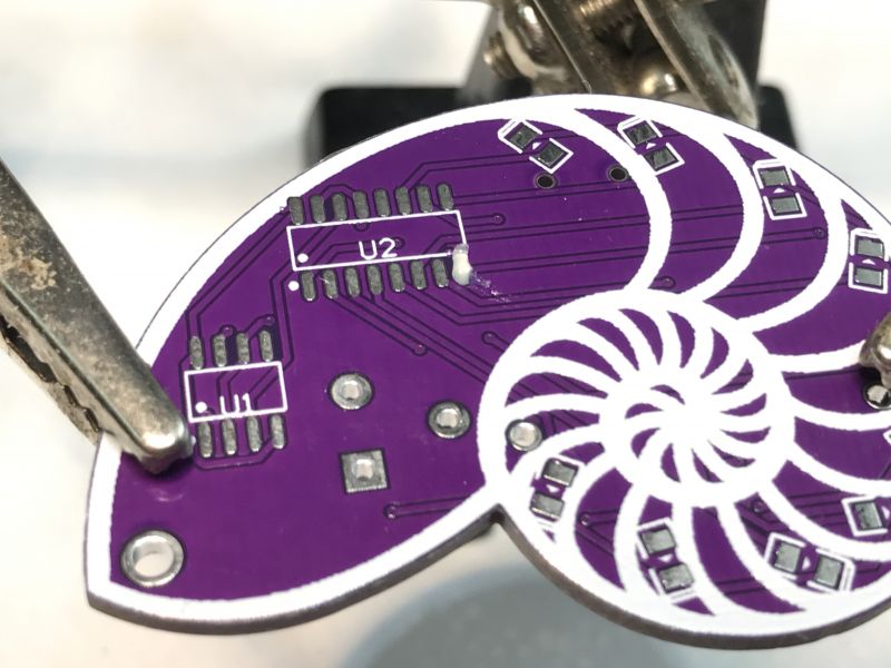
We start soldering - according to the instructions. First I clean the PCB once, then apply flux, then a bit of lead binder.
 .
.
 .
.
 .
.
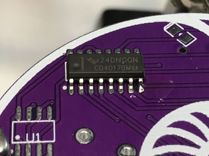
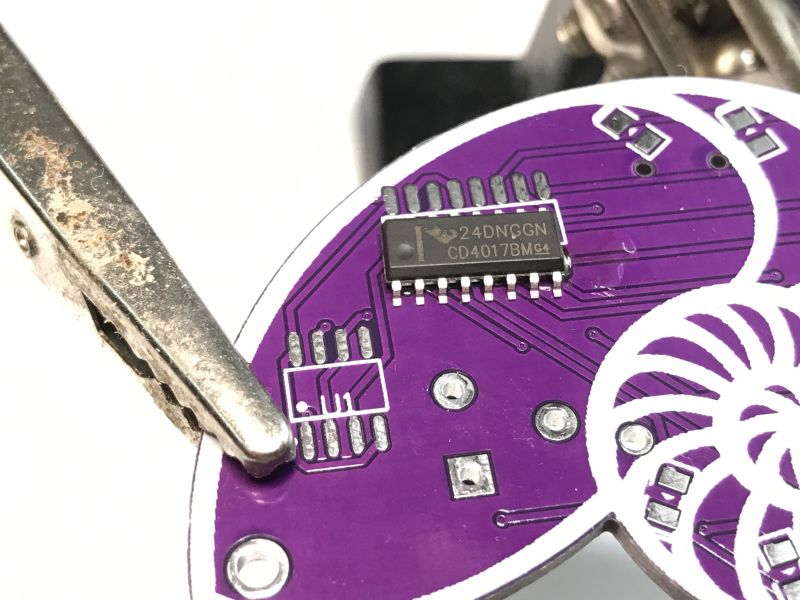
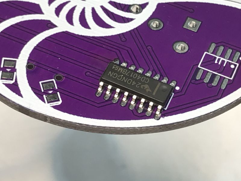
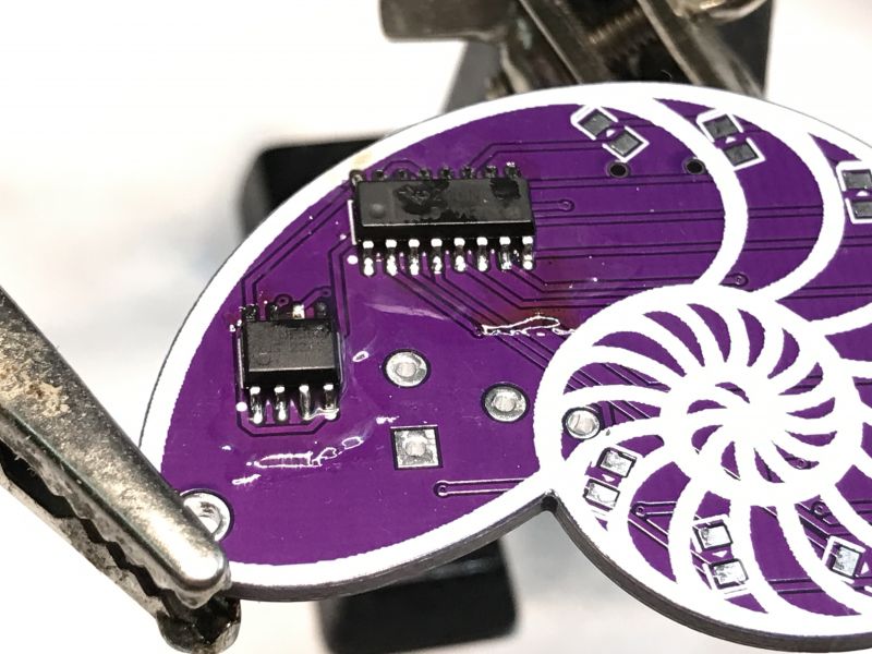
I then position the circuit. The dot on the layout marks the first pin. I match it to the dot on the PCB and grab its first pin.
 .
.
 .
.
 .
.
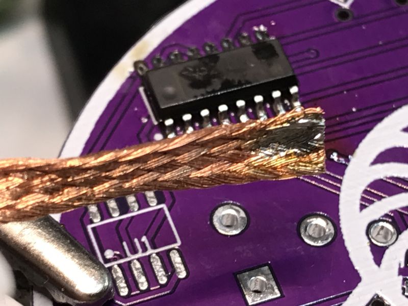
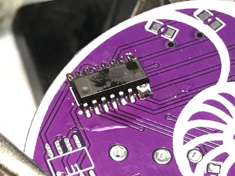
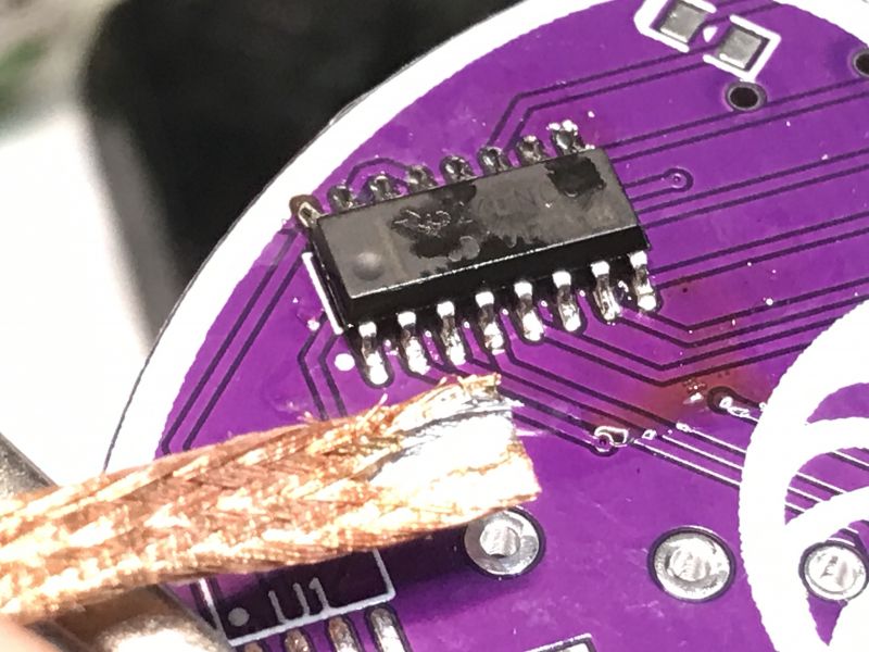
I grab the opposite leg (flux, binder) and then solder the others using the drag soldering method, passing the soldering tip over the legs. The binder melts and catches them, I remove the bridges this way, and if any short circuit remains anyway, I remove it with a braid.
 .
.
 .
.
 .
.
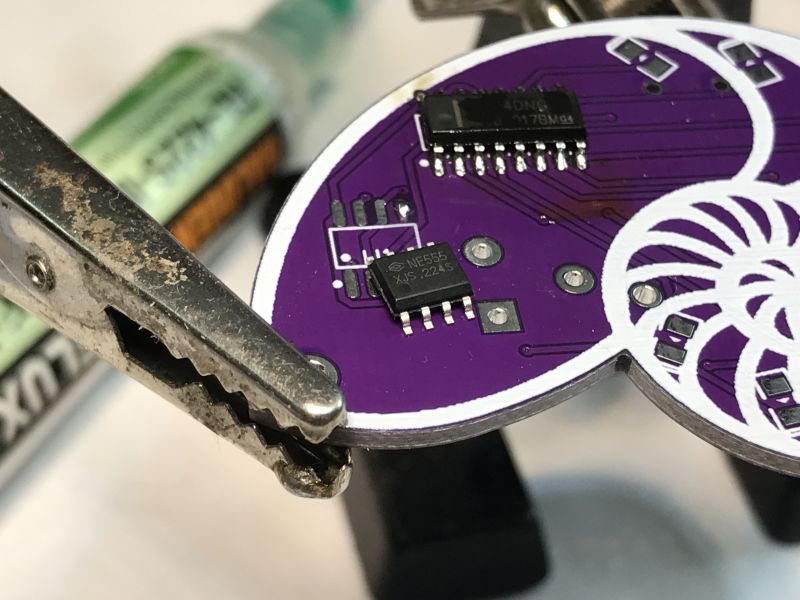
The second circuit (NE555) analogously:
 .
.
 .
.
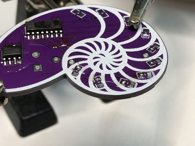
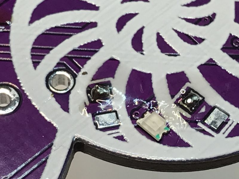
I then soldered the diodes. The double line on the board corresponds to the 'coloured' end of the diode - the cathode. For convenience, I prepared several pads.
 .
.
 .
.
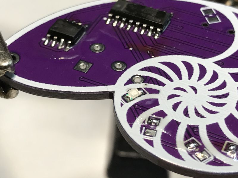 .
.
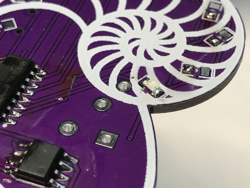 .
.
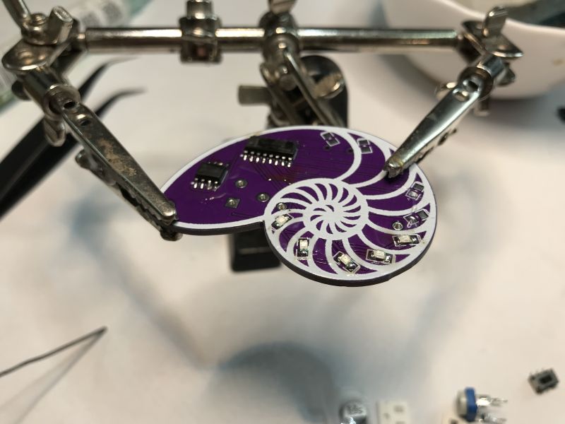 .
.
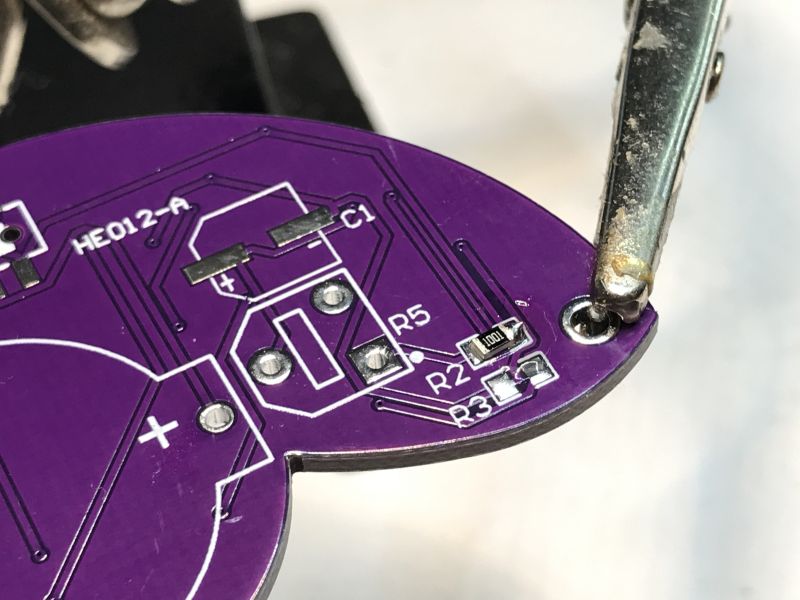
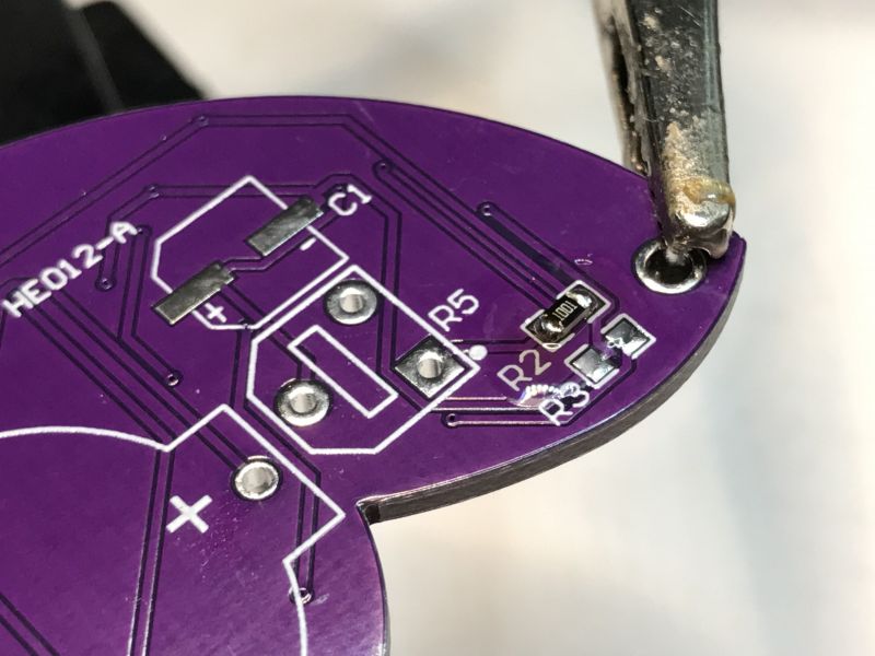
Then the resistors - analogously. Here we have two values, not to be confused. 1kΩ, which is the designation 1001 and 100Ω which is the designation 101 or 1000.
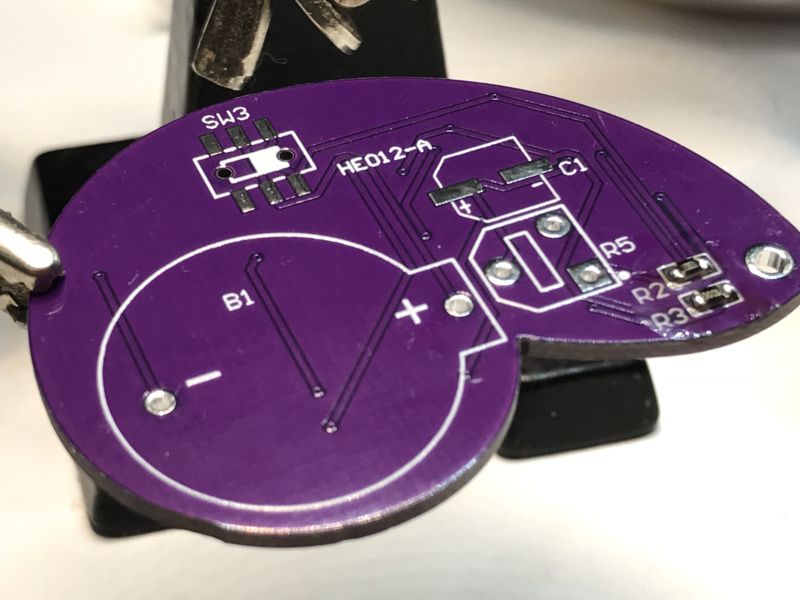 .
.
 .
.
 .
.
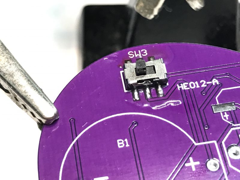
Now the switch. At it, be careful with the flux - so it doesn't get inside....
 .
.
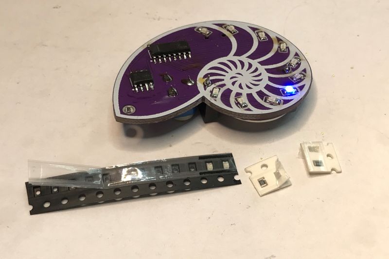
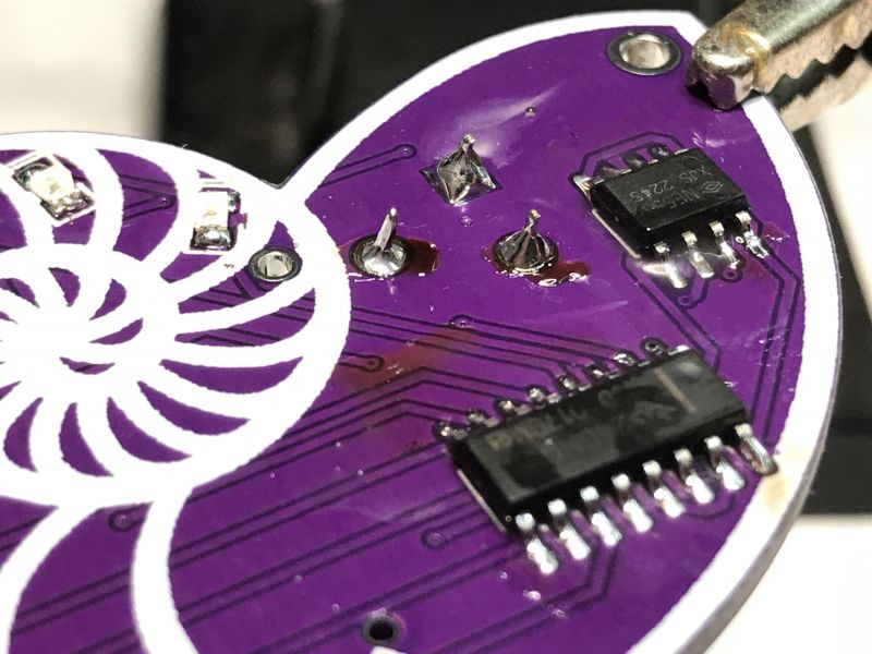
As usual - I grabbed a leg, soldered the others. Potentiometer and battery slot left:
 .
.
Ready, but before switching on, check for short circuits or cold soldering or bad soldering.
 .
.
The potentiometer, as you may have guessed, adjusts the speed of the light.
The circuit itself is a classic 'flowing light' on an NE555 and CD4017. The NE555 generates a clock pulse and the CD4017 counts it and lights the corresponding diode.
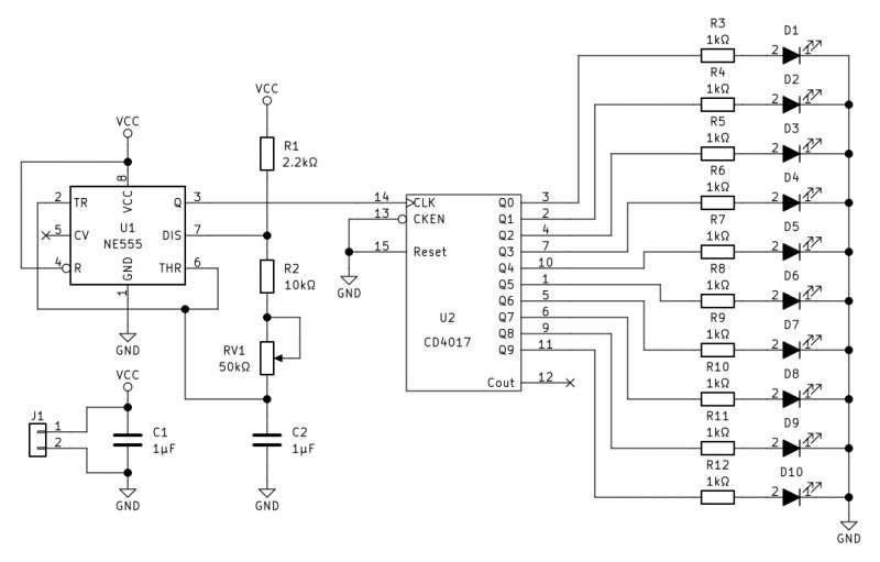
The version in the topic omits the LED current limiting resistors, this works because of the low supply voltage.
In summary , a simple and enjoyable toy to assemble. Perhaps there could be more of these elements, but would that be a plus? On the other hand, the impatient 'young able' may just want a kit that is easier to run, so more elements would be a disadvantage. Additionally, it can be pointed out here that the whole thing will work as long as the power supply, clock generator and counter are soldered well. Some of the diodes may be soldered wrong and it will still run.... and nothing teaches as well as correcting your own mistakes and looking for cold solders or short circuits, which are not difficult to find.
I myself, with my visual impairment, had to play with soldering this a bit, but I have my ways:
Phone as "microscope" and TQFP soldering - step by step video presentation .
That's it from my side, and how would you guys learn SMD soldering? Is it better to solder ready-made kits, or maybe just find an old (for example) laptop on the electro-junk and solder and solder transistors to it until you get the hang of it? Although this is of course a whole other level, because in a laptop the board is massive and will take a lot of heat before you even solder a resistor....


Comments
. My first contact with SMD was in 2007, when I started working at Jabil Circuit Poland in Kwidzyn. It was a short episode in the summer holidays between technical school and university. I worked there... [Read more]
An aesthetically pleasing end result. It is reminiscent of the electronic badges that some people used to prepare and wear at electronic events. [Read more]
One could think of a similar 'badge/toy' with the Elektroda logo. [Read more]
Cool. I once made a badge for my daughter for a preschool playdate. . Added after 3 [minutes]: [Read more]