Which WiFi controlled relay module for Home Assistant? ATLO-SW1-TUYA
 .
.
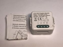
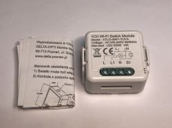
The ATLO-SW1-TUYA is another tiny (43x39x22 mm) relay module offering control of a single receiver via WiFi. It is mounted in a box and, in addition to WiFi, it can work with a classic bistable switch. Here I will show how to change its firmware to connect it to Home Assistant. The whole thing is available to buy for £30.
I got this unit from a reader along with a whole set of similar relays for several rooms - I just uploaded the firmware at his request.
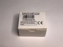
We start by unpacking. The product designation is ATLO-SW1-TUYA, and you can also see the name of its importer, although this is less important here as many shops sell similar products.
 .
.
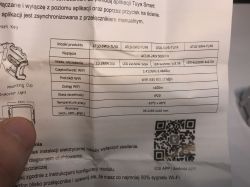
The kit also comes with Polish-language instructions for assembly and pairing with Tuya. Pairing will not be necessary for us in this particular case.
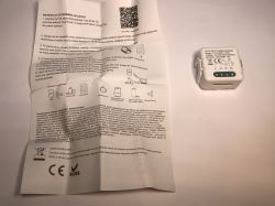
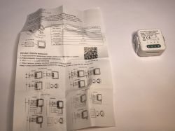 .
.
The product itself has an additional buckle which makes it easy to install:
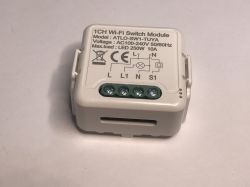
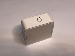 .
.
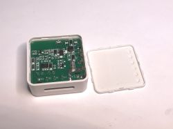
Time to look inside and change the firmware .
 .
.
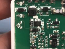
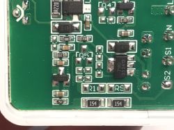
The power section is again on a BP2525, which is a non-isolated step-down converter. This means that there may be mains potential across the PCB (and WiFi module). Then there is a 3.3V LDO powering the WiFi module.
 .
.
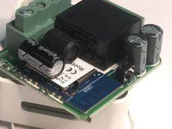
The relay was set 'on its side' to reduce the height of the product. The module used here is a CB3S (WiFi + BT) based on the BK7231N.
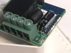 .
.
It's time to change its firmware so that it's cloud-free and connected to Home Assistant.
We upload OpenBeken: https://github.com/openshwprojects/OpenBK7231T_App
Download the flasher: https://github.com/openshwprojects/BK7231GUIFlashTool
We will need to solder 3.3V, GND, RX and TX. We will use a USB to UART converter for programming.
Here is the pinout of the module (bottom view!):
 .
.
So first we solder the RX and TX - whittle down the pins, wires, solder:
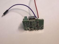
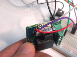 .
.
Now we need to connect the power supply. We basically have two options:
- feed 3.3V from our LDO to the 3.3V line (or the 3.3V pin of the WiFi module)
- connect 5V to the input of the LDO (this will give us 3.3V at its output)
Do as you wish, the AMS1117 leads are in the network.
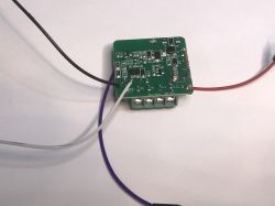
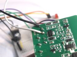 .
.
We follow the flasher instructions - start reading the flash (this will give us the GPIO configurations) and disconnect the 3.3V momentarily.
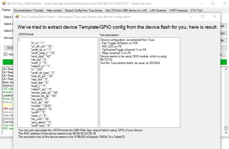 .
.
Success! Tuya JSON is:
Code: JSON
Verbal description:
Device seems to be using CB3S module, which is BK7231N chip.
- Relay (channel 1) on P6
- WiFi LED on P9
- TglChannelToggle (channel 1) on P8
- Pair/Toggle All Pin on P26
OBK template:
Code: JSON
Instructions for importing the template:
HA Discovery Instructions:
Other related material on YT Elektroda.com:
https://www.youtube.com/@elektrodacom
Project repository:
https://github.com/openshwprojects/OpenBK7231T_App
After the import, it is still a good idea to add the PowerSave 1 command to the autostart, as these types of gadgets have weak power supplies and capacitors damage quickly in them.
In summary , this was another easy to reprogram product. We didn't even have to guess the role of the GPIO, as my flasher read and decoded everything correctly. After this short operation we can enjoy a fully cloud-independent relay controlled by WiFi.
Thanks to Bartek for providing me with a set of hardware to change the firmware, hopefully it will work well with your Home Assistant.
I've been monitoring the inside of these types of devices for a good few years now and fortunately they are still fully 'programmable', so if anyone wants cloudless automation at a low cost then by all means go ahead and buy.
And how do you use this type of product, do you change the firmware, do you like the manufacturer's cloud, or do you buy something that can already work locally on its own? .


Comments
I have something similar, different logo but looks identical. Similar modules are probably mainly a matter of the chip fitted? [Read more]
Rather, the interior will be more or less as I have shown. It's just that the importers are pulling these products and adding their logos on them. Show pictures (maybe from the inside too). [Read more]
https://obrazki.elektroda.pl/7562280100_1748872003_thumb.jpg . I also use modules of this type. They are described as OXT. They come in various configurations. D operating one bulb and one switch,... [Read more]
. This is the kind of thing I have - connected already, photo from the seller's website. https://obrazki.elektroda.pl/3880254000_1748934664_thumb.jpg . It is powered by applying phase (L) through... [Read more]
OXT I have also already programmed some: Powerless relay on WiFi - OXT SWT10 - interior, programming . @sq3evp monitor that smart switch what you have and let me know if it breaks down, I've had instances... [Read more]
. It's going to be hard because it's on a suspended ceiling. You have worried me but I will monitor, thanks for the warning. So far I can't hear the crickets, just the relay switching on/off on the... [Read more]
@sq3evp, maybe nothing to worry about in the meantime. Of my 5 installed OXTs, in two years of use only one relay failed, twice. It was offline and unresponsive to the switch. It needed a hard reset in... [Read more]