logo elektroda
logo elektroda
X
logo elektroda

ATLO-TB2-TUYA - silent double light switch with WiFi control under Home Assistant

p.kaczmarek2 726 2
ADVERTISEMENT
Treść została przetłumaczona polish » english Zobacz oryginalną wersję tematu
📢 Listen (AI):
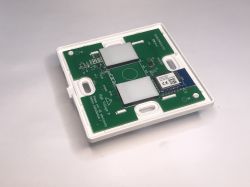
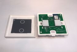
  • Interior of ATLO-TB2-TUYA touch switch with detached front panel beside .
    Which silent light switch for the Home Assistant? Here is another product compatible with our Polish open source IoT software - ATLO-TB2-TUYA. This time without the relays. I will present here the double version, i.e. with two buttons, although you can get the same thing in a single or triple version. The price of the product is around £50 - depending on the number of buttons. You can get it cheaper by importing from China. This particular switch does not require a neutral wire to work. Let's start with the contents of the kit:
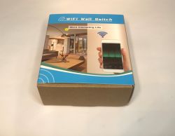
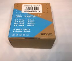
    WiFi Wall Switch product box with graphic and smartphone on the lid Box of ATLO-TB2-TUYA light switch with printed configuration options .
    Included is a capacitor, counteracts the glowing of the LEDs, also necessary for operation without neutral wire.
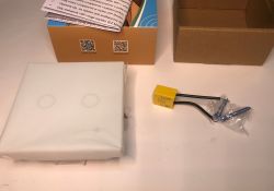
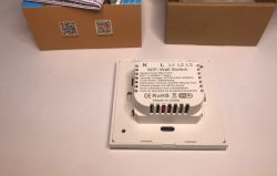
    ATLO-TB2-TUYA switch set with capacitor and mounting screws Rear view of ATLO-TB2-TUYA WiFi light switch with labeled connectors .
    We also get two screws for mounting to the box.
    Installation and pairing instructions from Tuya:
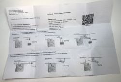
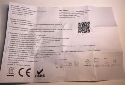
    Installation manual and wiring diagram for ATLO-TB2-TUYA switch Installation and pairing guide for ATLO-TB2-TUYA switch with Tuya Smart app. .

    Let's get straight to the inside of the product. The front panel is removable.
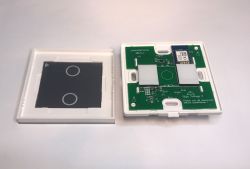
    Disassembled touch light switch with CB3S module and two-button front panel Interior of ATLO-TB2-TUYA double touch light switch with WiFi module
    Designation: 3T86CBWIFIAV3.1
    The whole is based on the CB3S module:
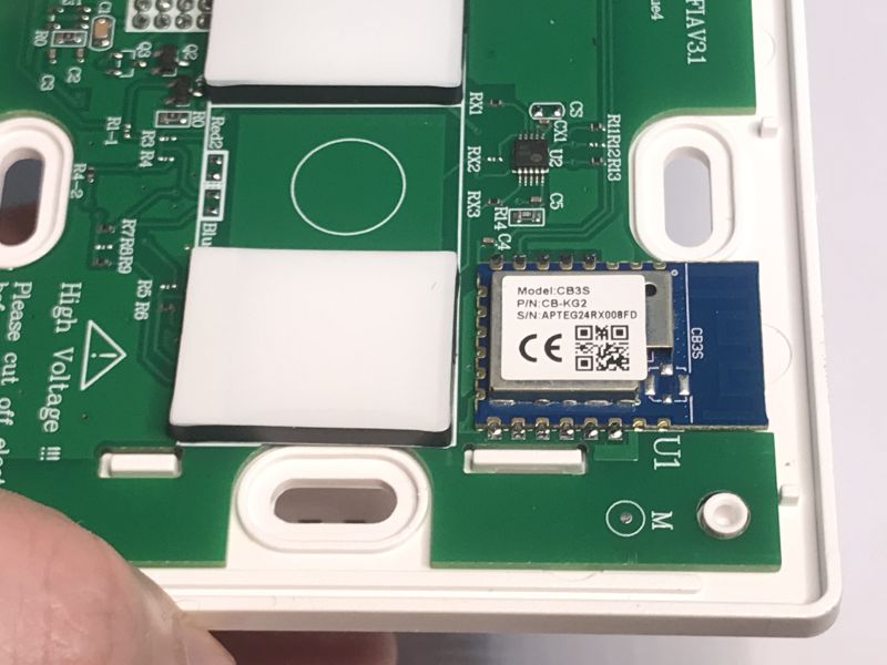
    CB3S module mounted on control PCB in ATLO-TB2-TUYA wall switch .
    Then we will change its software. Bottom view:
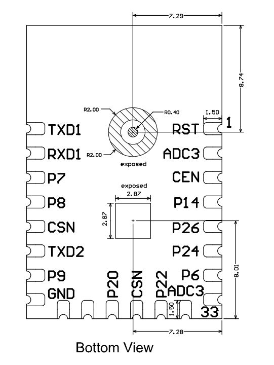
    Bottom view diagram of CB3S module with labeled pins and exact dimensions .
    That little chip on the board is not the TuyaMCU - it's a touch button controller.
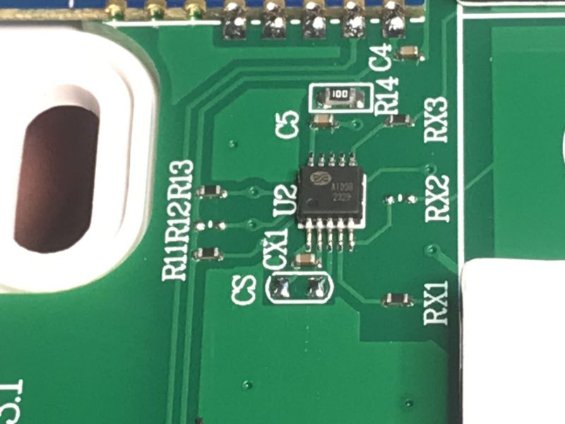
    Close-up of A1038 chip on green PCB with RX and CS labels around it .

    Let's check the second board out of curiosity.
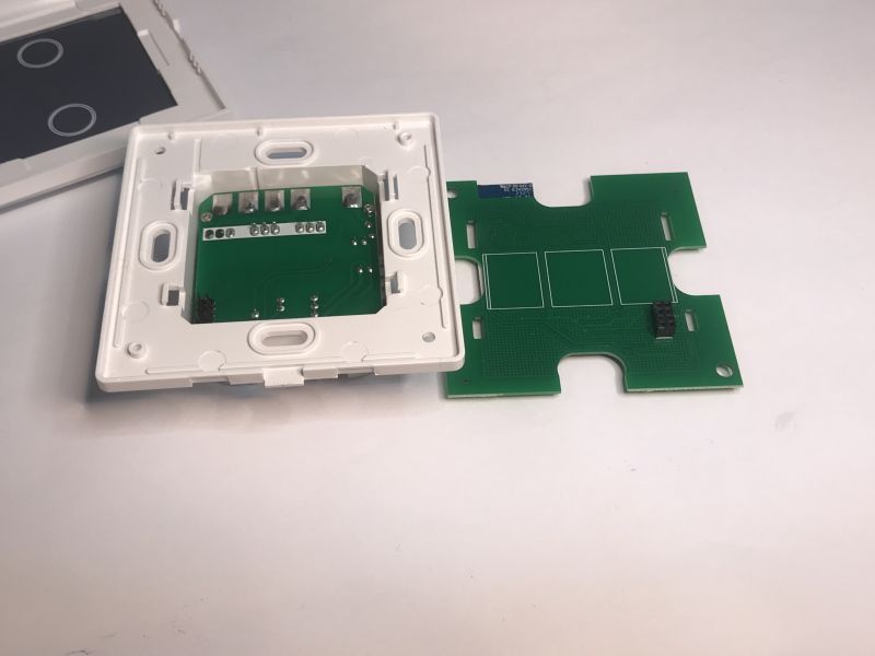
    PCBs of disassembled ATLO-TB2-TUYA touch light switch lying separately .
    You can immediately see that there are no relays here, so there will be no characteristic clicking.
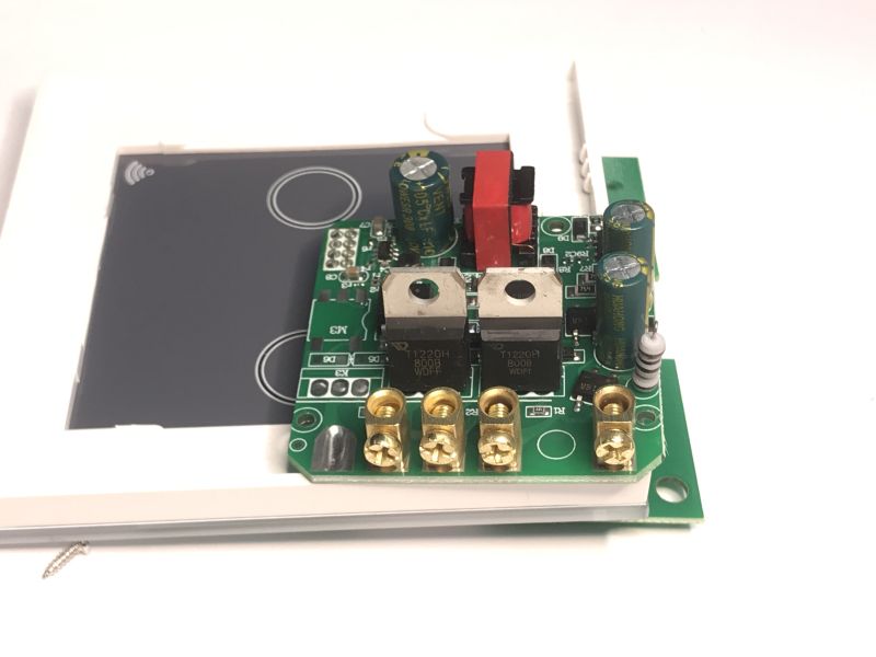
    Interior of the ATLO-TB2-TUYA dual touch switch with visible electronics .
    The T1220H 800B is a triac with a current of up to 12A:
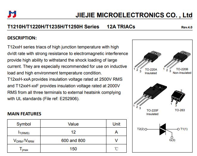
    Excerpt from JIEJIE T1220H triac datasheet with specs and package diagrams .
    Each of the triacs is separately controlled by a MOC3053 optotriac.
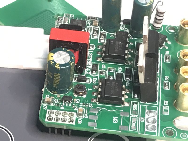
    Triac control module with capacitor and MOC3053 on ATLO-TB2-TUYA PCB .
    There is room on the board for a third pair:
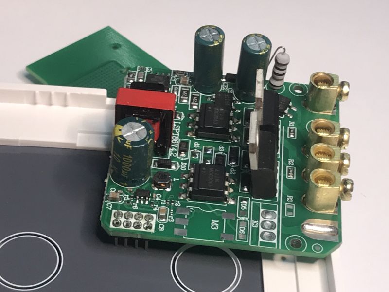
    Control board of ATLO-TB2-TUYA touch switch with visible components .
    In addition there is a CSC7136B based power supply on the board.
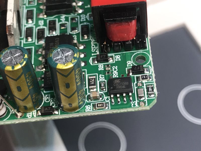
    Close-up of PCB with two capacitors and power IC labeled CSC7136B .
    Some additional photos:
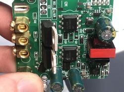
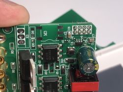
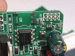
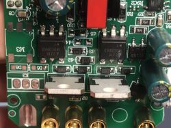
    Close-up of ATLO-TB2-TUYA PCB with visible triacs and capacitors Close-up of PCB with capacitor, triac, and MOC3053 optotriac chip Close-up of PCB with capacitor, MOC3063 optotriac, and labeled components. Close-up of PCB with T1220H triacs and MOC3053 optotriacs .

    ADVERTISEMENT


    Software change .
    Just use our flasher:
    https://github.com/openshwprojects/BK7231GUIFlashTool
    All with instructions on the project page - you can also have a look at the related material on Youtube Elektroda.com (search under CB3S or better CB2S):
    https://www.youtube.com/@elektrodacom
    You need four cables - ground, 3.3V and RX and TX.
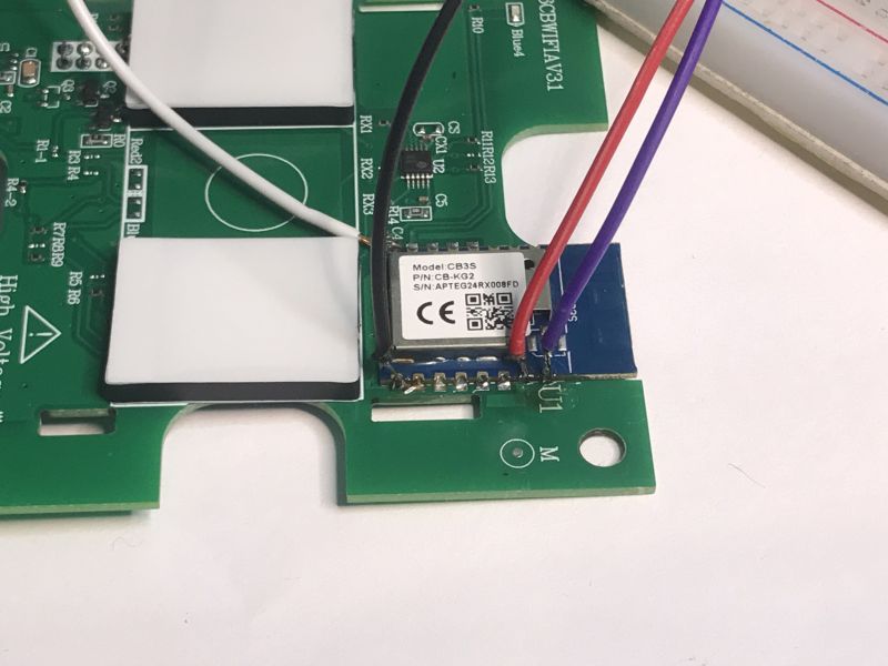
    Close-up of CB3S module connected with four wires on ATLO-TB2-TUYA PCB .
    The whole circuit (USB to UART converter with an additional 3.3V LDO on the contact board):
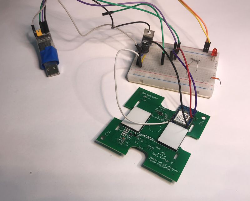
    ATLO-TB2-TUYA switch board connected to breadboard and USB-UART adapter .
    First we read the firmware. Flasher correctly discovers the configuration:
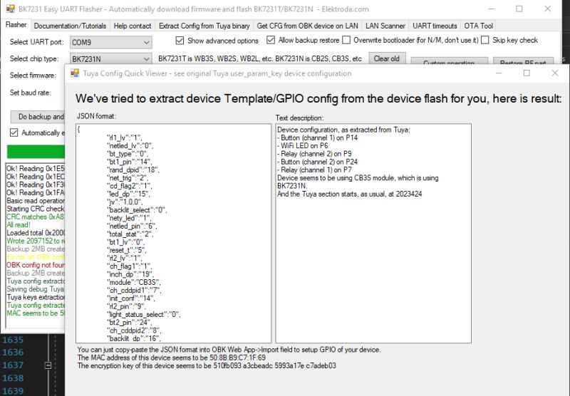
    Screenshot of BK7231 GUI Flash Tool showing GPIO config extracted from CB3S module .
    JSON Tuya:
    Code: JSON
    Log in, to see the code
    .
    Verbal description:
    
    Device seems to be using CB3S module, which is BK7231N chip.
    - Relay (channel 1) on P7
    - Relay (channel 2) on P9
    - WiFi LED on P6
    - Button (channel 1) on P14
    - Button (channel 2) on P24


    OBK template:
    Code: JSON
    Log in, to see the code

    Import template:


    Import template.
    Pairing with HA:


    Import.

    In summary , this product is distinguished by the absence of the characteristic click when switching. Just right for people who find it annoying or distracting, although someone else might say it's a downside because there is no 'beep' to tell you the circuit has been closed. Just whether such a 'signal' is needed? Rather, turning on a light is sufficient - as long as there is no problem with the bulb.
    Changing the firmware was again very easy, there was no need to desolder the CB3S, and our flasher discovered the hardware configuration itself, so we didn't have to guess the GPIO.
    The front panel of the device is also quite OK, with no disfiguring prints or unnecessary logos.
    Is it worth it? This is your decision. In your opinion, is it worth reaching for such a "silent" version of the programmable light switch?

    Cool? Ranking DIY
    Helpful post? Buy me a coffee.
    About Author
    p.kaczmarek2
    Moderator Smart Home
    Offline 
    p.kaczmarek2 wrote 12893 posts with rating 10708, helped 599 times. Been with us since 2014 year.
  • ADVERTISEMENT
  • #2 21640797
    kris1966
    Level 18  
    I have a similar one with relays. It even works but you have to focus on where your finger is touching. A normal bang with your paw, elbow, forehead and it worked and here it doesn't. I tried combining the three touch fields together but it didn't work very well. I don't know about this one but mine were very heavily backlit. I tried applying various films and patches but the effect was unsightly. In the end I added an smd resistor to each diode by cutting the paths but this too was not easy to find a convenient place. This capacitor causing the current to flow causes heat to be emitted in the switch (but I don't know how many watts of loss it is). And does anyone know how this RF works because I have one but don't know how or what to pair it with or which way. Logically it seems to be TX and I would prefer RX to switch off by remote control.
  • #3 21640807
    p.kaczmarek2
    Moderator Smart Home
    Which RF? This switch here does not have RF, although the forum has already shown WiFi+RF switches, such as those that pair with universal remotes. From what I remember, they have a receiver and the remotes have a transmitter, each remote has a unique code, so when you pair it, the switch "learns" the code of the remote and then responds to it. You press the touch for a longer time, the buzzer sounds, you press a button on the remote, the switch or rather the circuit in the soic tiny (not the WIFI module!) remembers this code and from then on responds to it.

    Here it was about RF:
    Wifi QTouch switch plugged into L wire only - test, interior, schematic .
    Helpful post? Buy me a coffee.
📢 Listen (AI):
ADVERTISEMENT