Four-slot strip with USB compatible with Home Assistant? TSL-PS-F4U-01-W
TL;DR
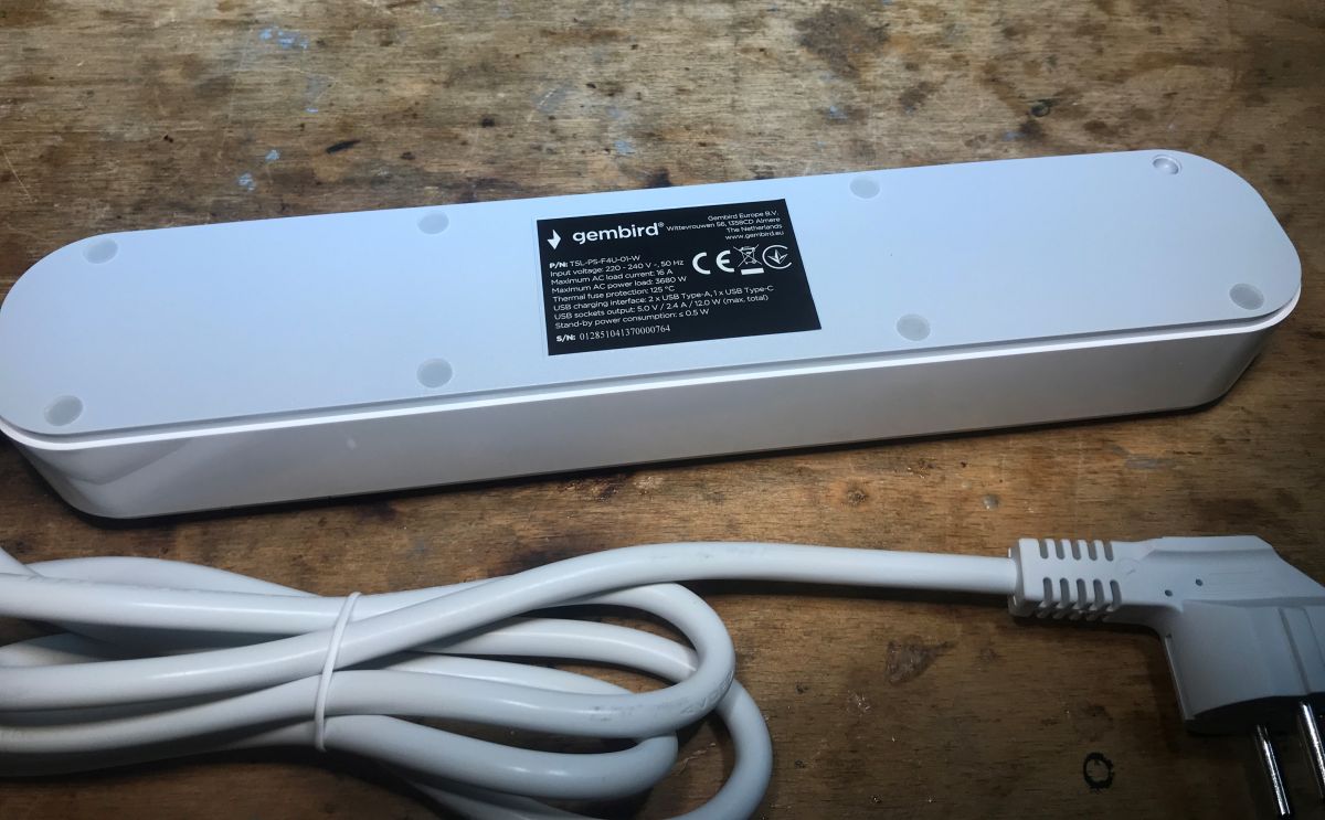
- Gembird TSL-PS-F4U-01-W is a four-socket 230V power strip with two USB ports, modified for local Home Assistant control.
- It uses a CB2S module with a BK7231N chip, and OpenBeken is flashed in-circuit without soldering the module out.
- The strip costs around PLN150, and the USB section is rated at up to 2.4A.
- After the firmware change, it works with Home Assistant, but USB charging stays plain 5V only with no QC, and deeper disassembly is awkward.
Generated by the language model.
 .
.
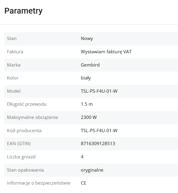
Today we are plugging another product into Home Assistant. This will be the gembird TSL-PS-F4U-01-W power strip offering four separately controlled 230V sockets and two USB sockets with a current capacity of up to 2.4A. I'll show the inside of it here, and then discuss modifying it to work locally with Home Assistant. We will upload OpenBeken onto it.
The whole thing is available to buy in our country for around PLN150. Information from the seller:
 .
.
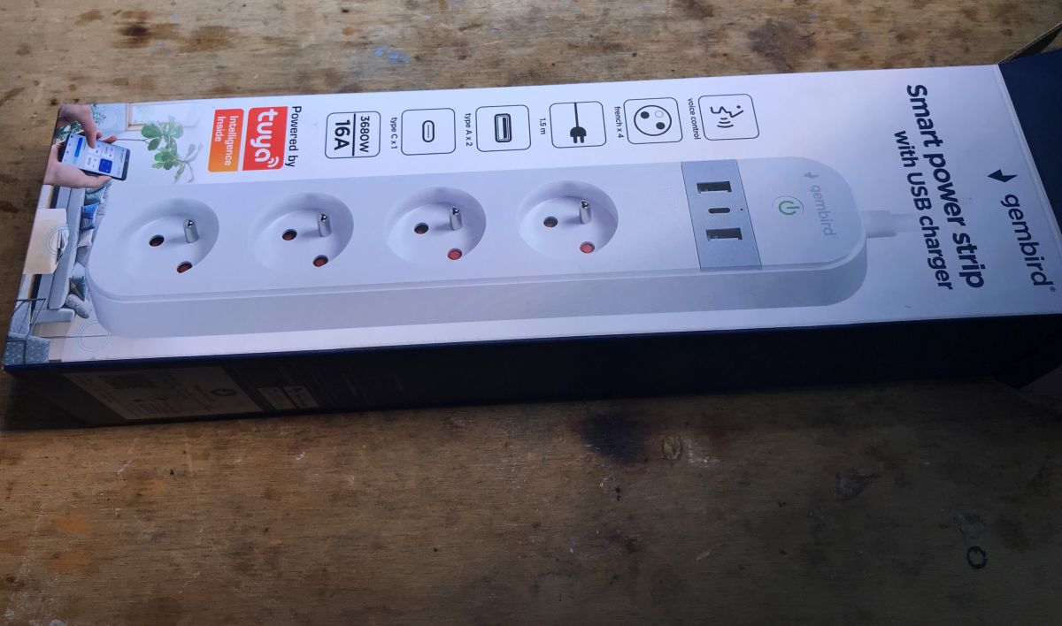
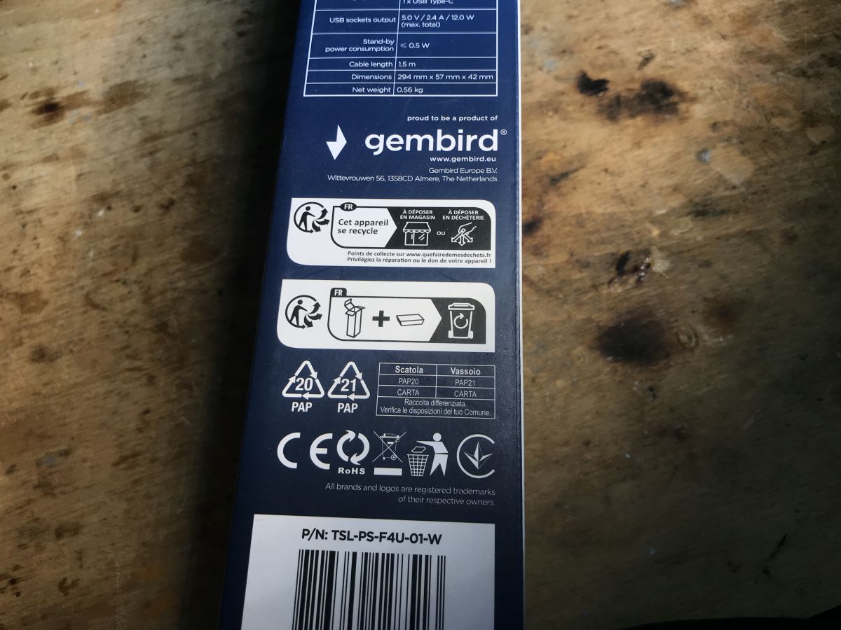
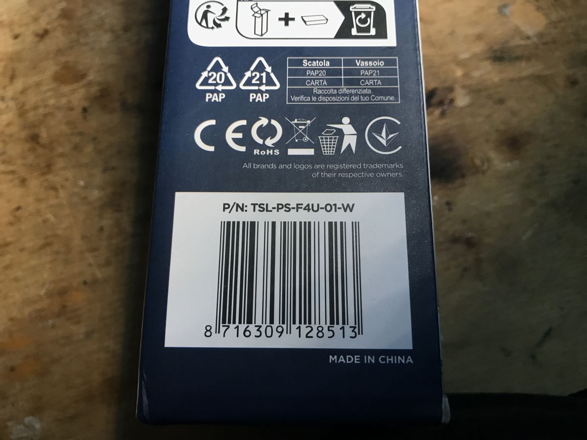
Here is the box received:
 .
.
 .
.
 .
.
 .
.
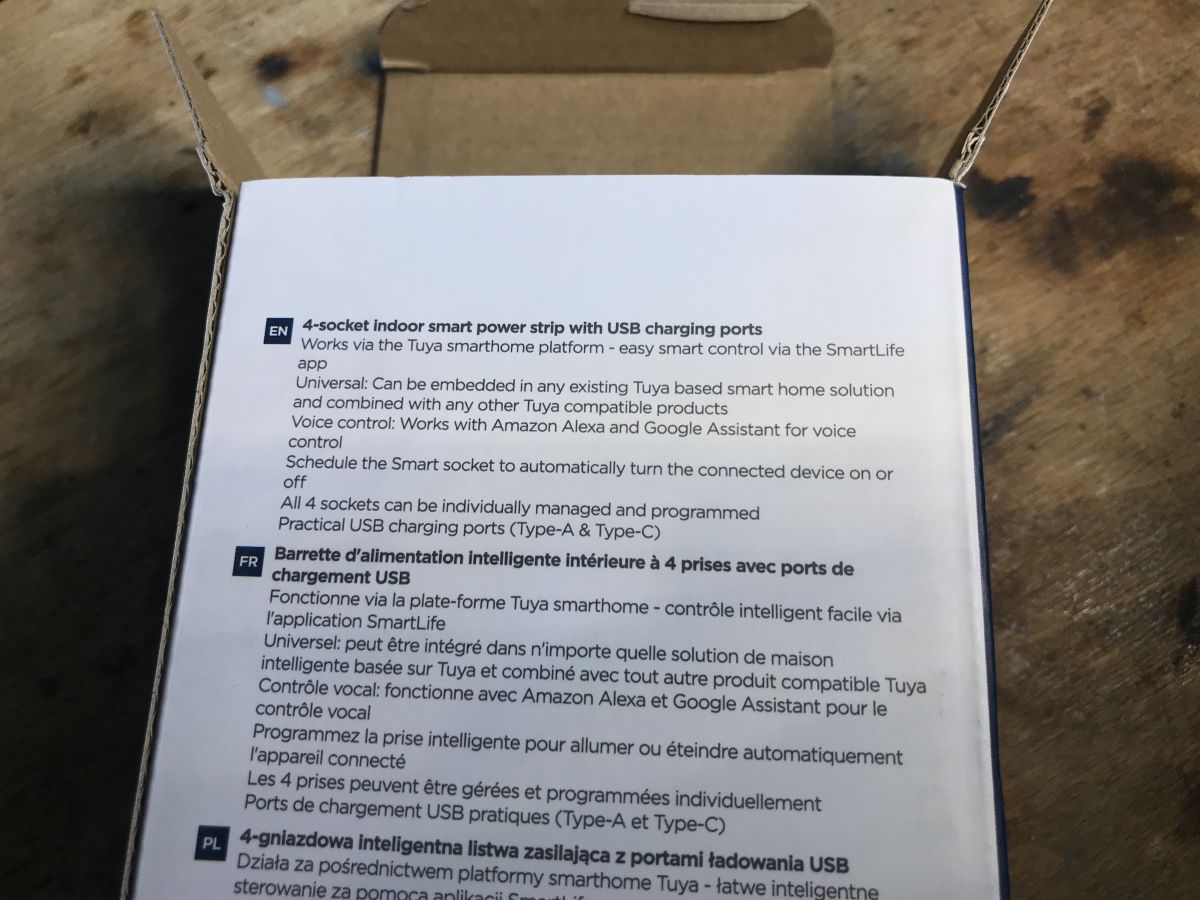
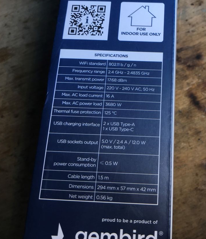
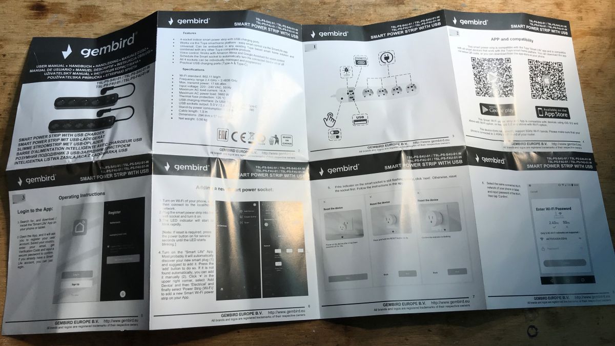
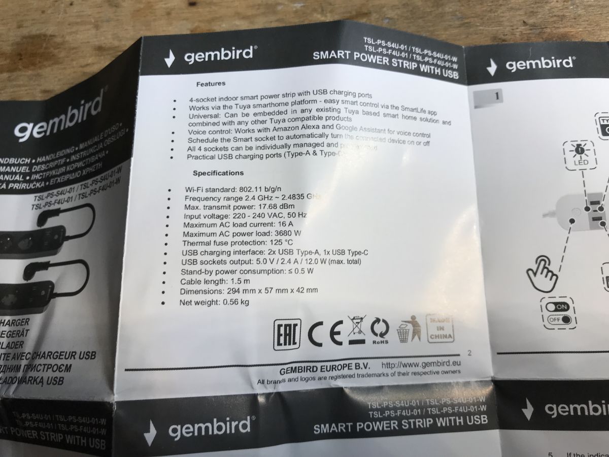
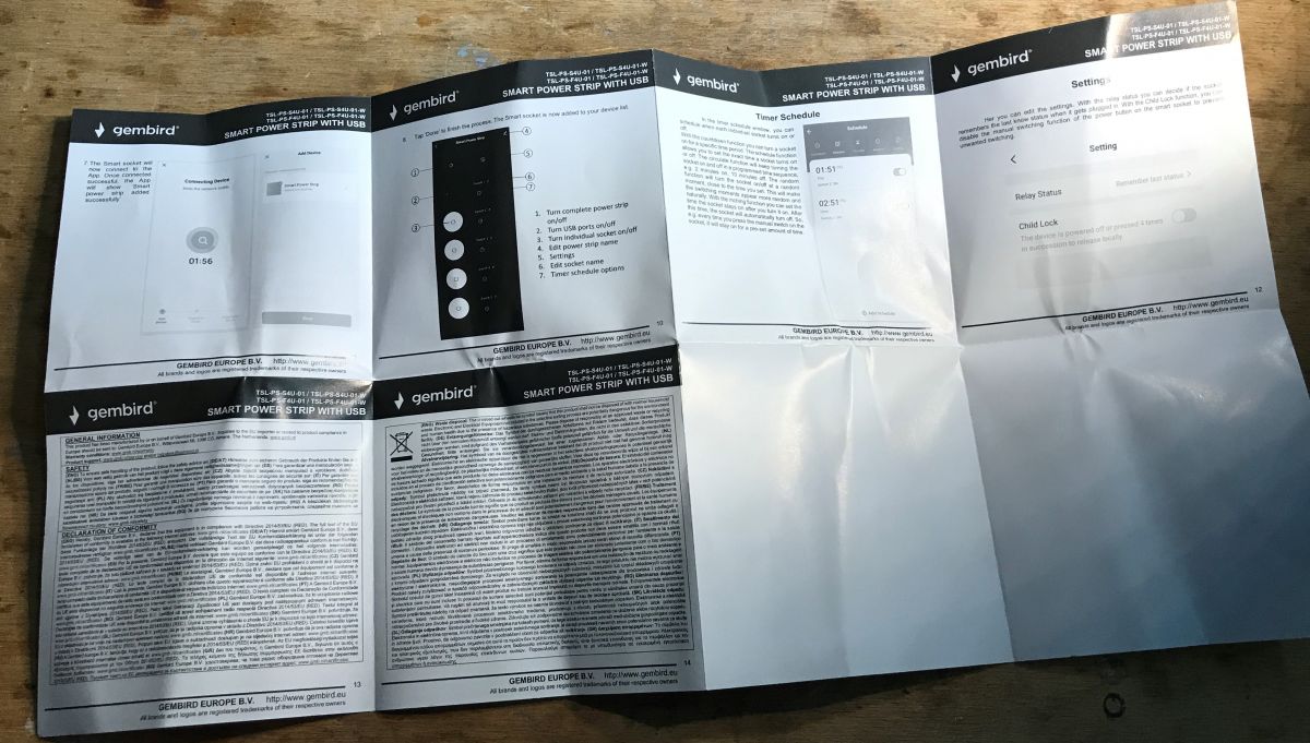
Instructions:
 .
.
Programming TSL-PS-F4U-01-W .
This product normally works with Tuya, but you can change the firmware and run it with Home Assistant (without the cloud).
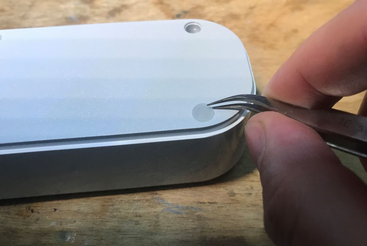
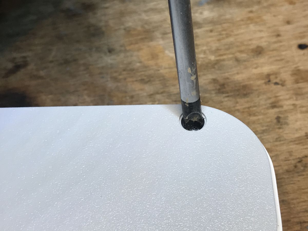
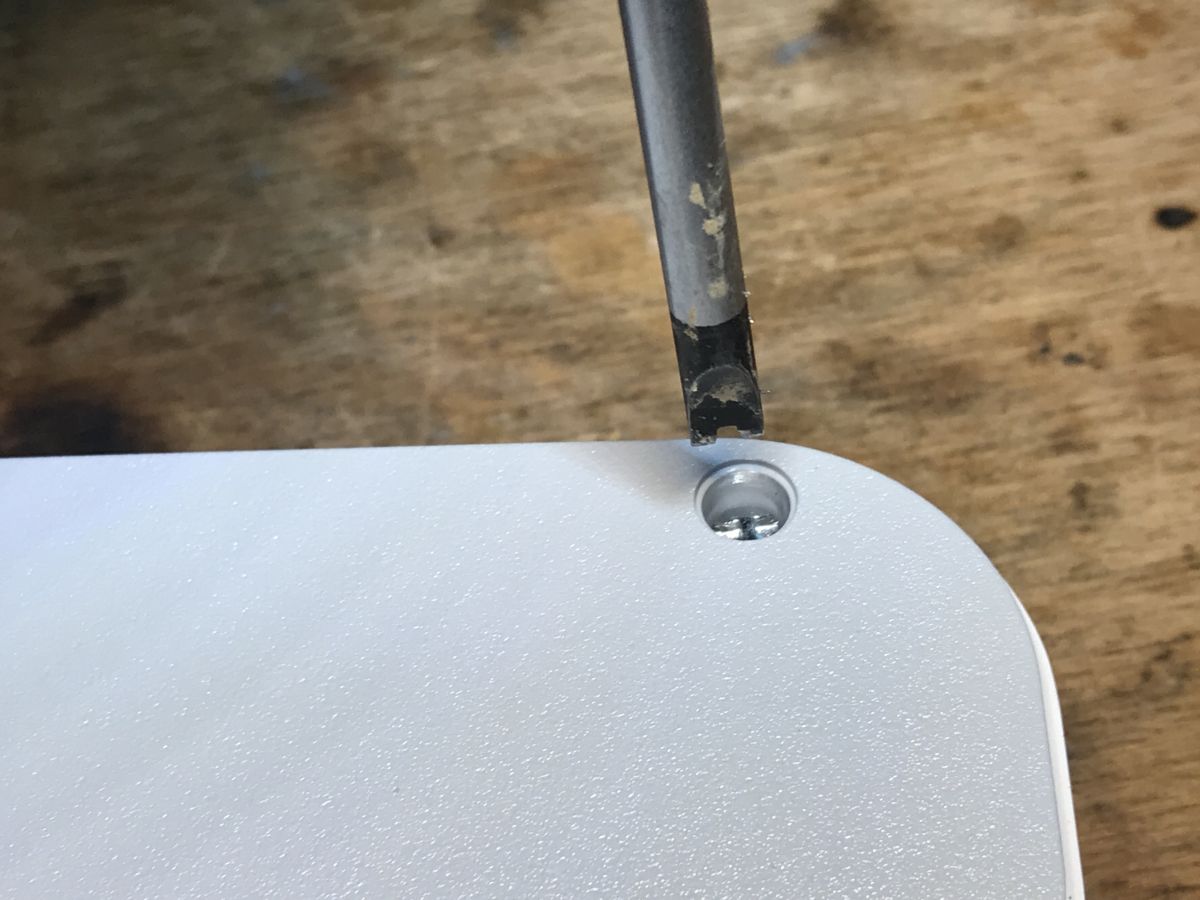
For the strip, first remove the feet/rubbers and then remove the screws with a flathead screwdriver, parted in the middle, that is a spanner type.
 .
.
 .
.
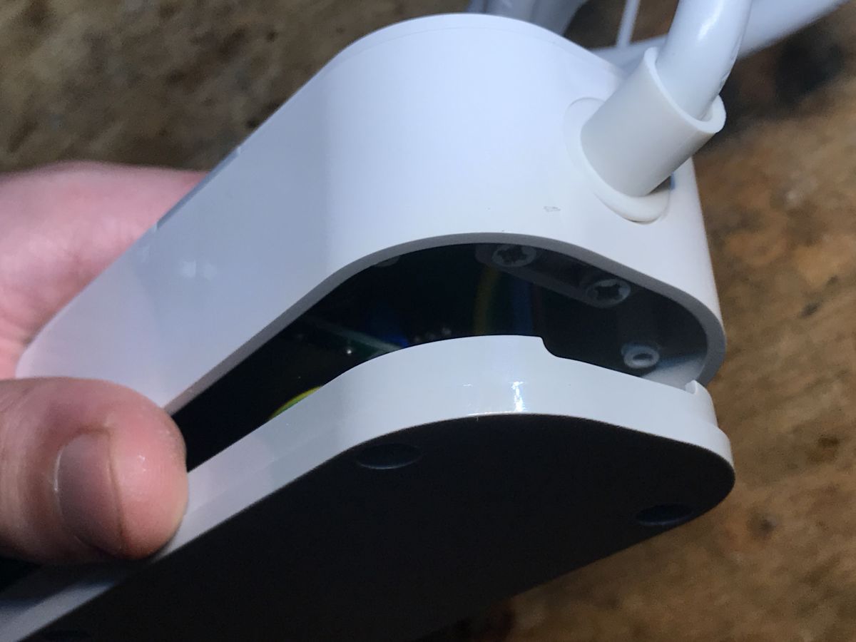
This is how we get inside:
 .
.
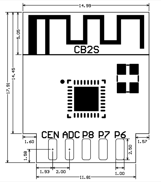
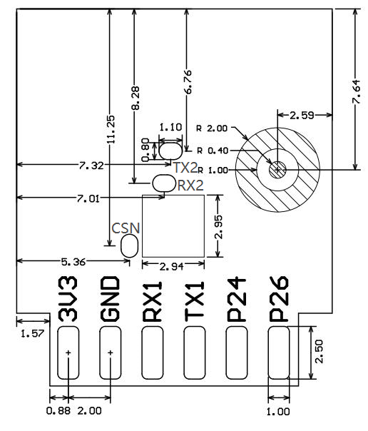
The board cannot be removed, but I guessed from the pads that there is a CB2S module inside:
 .
.
Outputs, quoting documentation:
| Pin number | Symbol | .I/O type | Function | ||
| 1 | 3V3 | P | P | Power supply 3V3 | |
| 2 | |||||
| 2 | P6 | I/O | Support hardware PWM and correspond to P6 of the IC | ||
| 3 | GND | P | Power supply reference ground | ||
| 4 | P7 | . I/O | Support hardware PWM and correspond to P7 of the IC | ||
| 5 | RX1 | I/O | UART_RX1, which is used for receiving user data and corresponds to P10 of the IC. Do not pull it up. By default, the MCU serial port should be in low-level or high-impedance state. | ||
| 6 | P8 | I/O | Support hardware PWM and correspond to P8 of the IC | ||
| 7 | 7TX1 | I/O | UART_TX1, which is used for transmitting user data and corresponds to P11 of the IC. Do not pull it up. By default, the MCU serial port should be in low-level or high-impedance state. | ||
| 8 | .ADC | I/O | ADC, which corresponds to P23 of the IC | ||
| 9 | P24 | I/O | Support hardware PWM and correspond to P24 of the IC | ||
| 10 | CEN | I/O | Reset pin | ||
| 11 | P26 | I/O | Support hardware PWM and correspond to P26 of the IC | ||
| Test point | Test point | RX2 | I/O | UART_RX2, which corresponds to P1 of the IC. This pin is not allowed to use. | |
| Test point | TX2 | I/O | UART_TX2, which is used for outputting logs and corresponds to P0 of the IC | ||
| Test point point | CSNI/O | Mode selection pin. If it is connected to the ground before being powered on, enter the firmware test mode. If it is not connected or connected to VCC before being powered on, enter the firmware application mode. It corresponds to P21 of the IC. |
This module is compatible with OpenBeken .
Firmware can be changed with our flasher:
https://github.com/openshwprojects/BK7231GUIFlashTool
You can also take a look at the tutorial from YT:
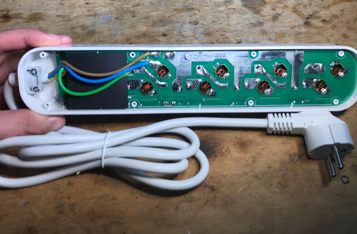
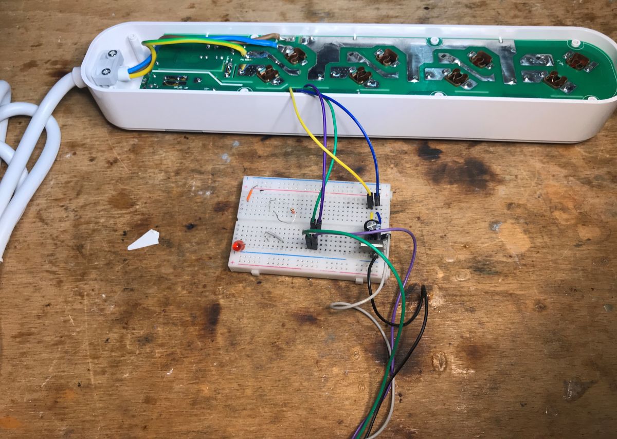
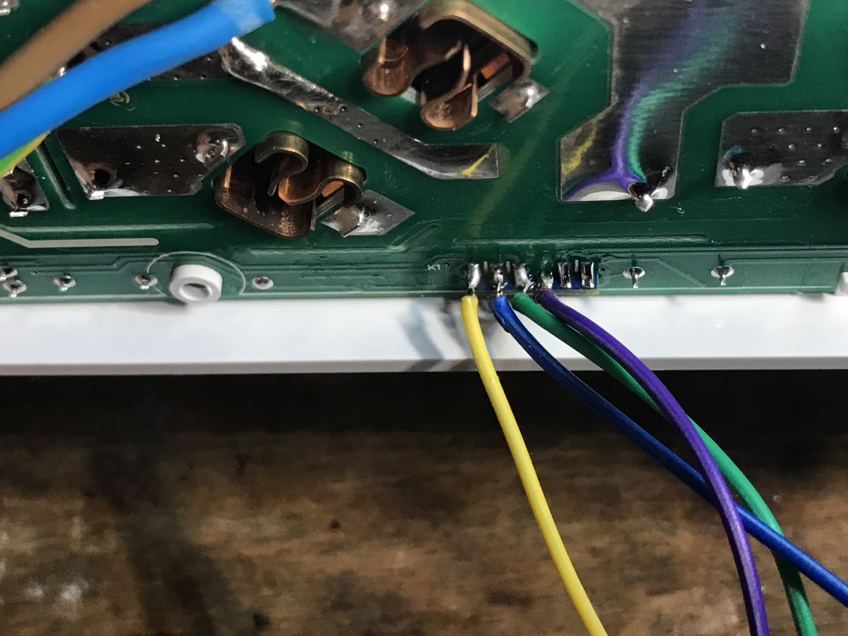
Here it is possible to program in the circuit, no need to solder out the CB2S. Just important that the product is disconnected from the mains:
 .
.
The aforementioned flasher discovers GPIO roles on its own:
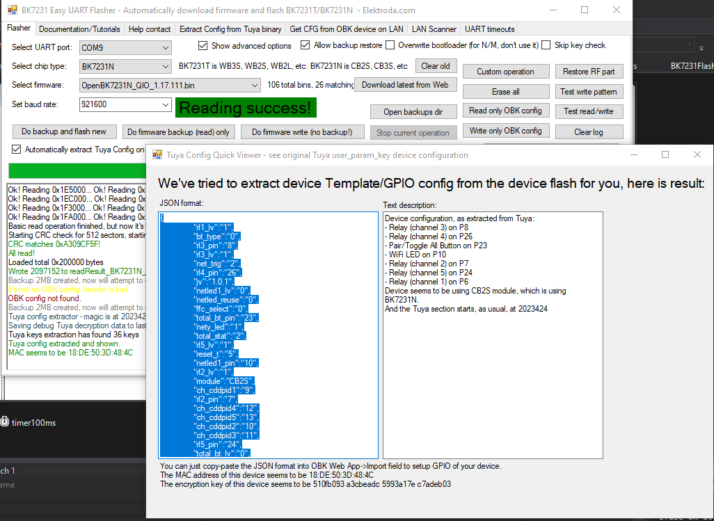
JSON Tuya:
Code: JSON
Verbal description:
Device seems to be using CB2S module, which is BK7231N chip.
- Relay (channel 1) on P6
- Relay (channel 2) on P7
- Relay (channel 3) on P8
- Relay (channel 4) on P26
- Relay (channel 5) on P24
- WiFi LED on P10
- Pair/Toggle All Pin on P23
Channel five here is USB, both ports are on one transistor.
Template OBK:
Code: JSON
Instructions for uploading the template:
Pairing with Home Assistant:
You can also set up separate single click, double click, triple click, etc. events here by setting the button to the Btn_ScriptOnly role, this will allow each relay to be controlled separately. Details (search: OnClick):
https://www.elektroda.com/rtvforum/topic3946427.html
https://github.com/openshwprojects/OpenBK7231T_App/blob/main/docs/autoexecExamples.md
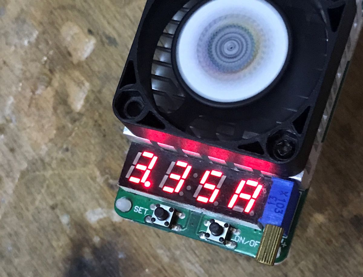
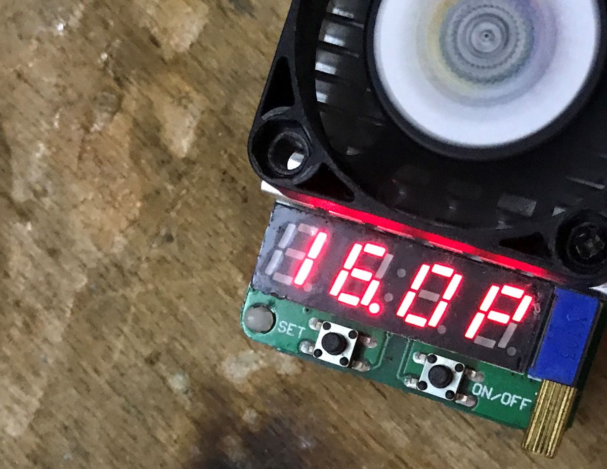
USB current capacity test .
It is indeed possible to draw some current, even over 3A (16W):
 .
.
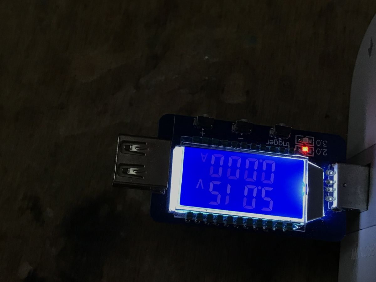
Unfortunately there is no QC here, just still 5V:
 .
.
Summary .
Probably a bit pricey for the non-QC version, but apart from that I have no major complaints. There is a problem with further disassembly (after removing the cover), but it's not needed to change the firmware, so I can't complain about that here. Once the firmware has been changed, the product works with Home Assistant and does its job well.
Do you see any use for such a programmable (automation) and remotely controlled (Home Assistant) strip? I remind you, each 230V socket has a separate relay..
PS: Manufacturer's copy of firmware:
https://github.com/openshwprojects/FlashDumps/commit/513afdc8cbc0663fec15591d997f6f56e300f96b

p.kaczmarek2 wrote 14607 posts with
rating 12622 , helped 654 times.
Been with us since 2014 year.
Comments
It can be useful to restart devices that have crashed. If you have a problem with WOL then you can do a computer wake-up - you need to set in the BIOS that the computer should turn on when the voltage... [Read more]
The vast majority of this type of product has a single button that works on an 'off/on all' basis in the app. I would love to see a strip with separate buttons. In OBK, you can script click, double... [Read more]
. I definitely recommend a VPN. The better routers have it built in. I put OpenVPN on the RPi, which also supports HA. There is also an OpenVPN client for mobiles. So all you need to do is run the VPN... [Read more]
Can you write a little more about this solution? It seemed to me that in order to set up a VPN tunnel, though, you need some kind of paid service - an intermediary - or an external IP (forwarded ports).... [Read more]
If we have a public IP and access to a router, all we have to do is forward the OpenVPN port on the router (UDP 1194 by default) to the machine with OpenVPN. If we have a floating IP we still need to take... [Read more]
I myself have been using OpenVPN for years for access to my home network and, among other things, also for HA, although I recently let that one go out via reverse proxy. Also recommended. If you don't... [Read more]
As there is a public IP (port forwarding) the matter is straightforward, this is not what I was asking, although I think it will be worth discussing on the forum as well. Maybe I will devote a topic to... [Read more]
. It's certainly worthwhile, as OpenVPN requires certificates, and there's a bit of fun to be had with generating them. You need to explain why you are generating CA ROOT and then descendant certificates. ... [Read more]
But there you go. Exactly the strip the author writes about. You can manage individual sockets and set schedules. https://obrazki.elektroda.pl/6477280100_1750328436_thumb.jpg . [Read more]
In that message, it refers to physical buttons, on the body of the device. In the application for this type of strip there is always a control for separate sockets and this is not new. [Read more]