logo elektroda
logo elektroda
X
logo elektroda

[BL602] BL602 PTBLU-W WiFi Module Pinout and Specs in EARU EAKCB-EWE-M Circuit Breaker

ProfAnderson  25 1794 Cool? (+6)
📢 Listen (AI):

TL;DR

  • The EARU EAKCB-EWE-M circuit breaker uses a PTBLU-W WiFi module based on the BL602 alongside a BL0942 energy-monitoring chip.
  • Tracing the module’s GPIOs exposed 21 pins plus 3 extra pins, and the main board uses 10 of them for LEDs, the button, bistable relay control, and BL0942 UART.
  • The breaker is rated up to 63A, while the relay itself is marked for 60A maximum.
  • OpenBK on BL602 starts at 192.168.169.1 in AP mode, and versions >=1.18.95 may need a 10-second delay before UART activation.
Generated by the language model.
Here's details and pinouts for the EARU model EAKCB-EWE-M circuit breaker, purchased from AliExpress in Jun 2025:
https://www.aliexpress.com/item/1005006189189642.html


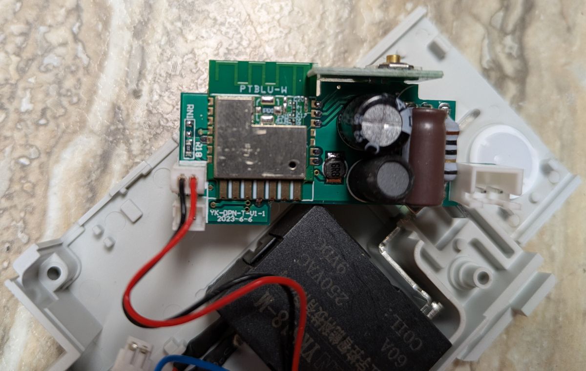
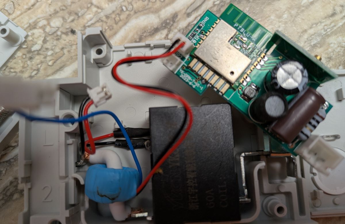
There's 6 rivets holding the case; you can just drill them out and then the case opens easily. The circuit breaker is rated up to 63A; the relay is marked at 60A maximum.

The rest of the construction looks very solid and easily capable of handling 60 amps.


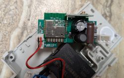
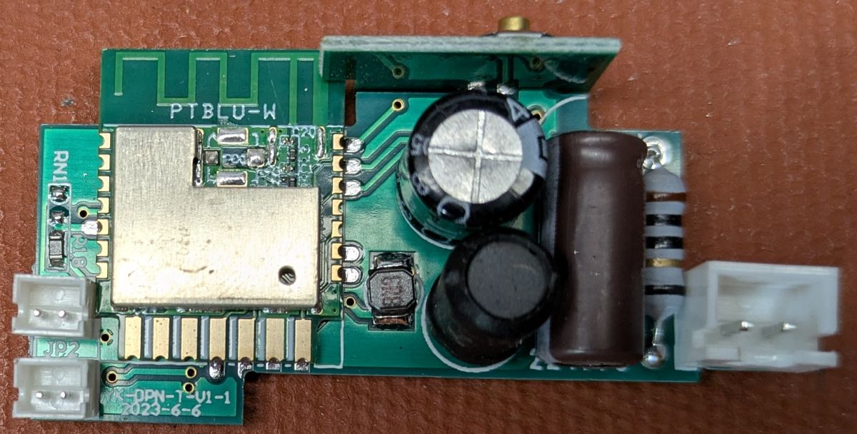
Apparently these devices previously used a PSF-B wifi module. This one has a wifi module PTBLU-W based on the BL602. The module is mounted on a circuit board labelled YK-DPN-T-V1-1 which is dated 2023-6-6. I could not find any specs on the internet for the wifi module.

The power supply has no transformer, so the module should never be powered by mains voltage while testing and measuring signals and voltages on the circuit board.

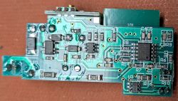
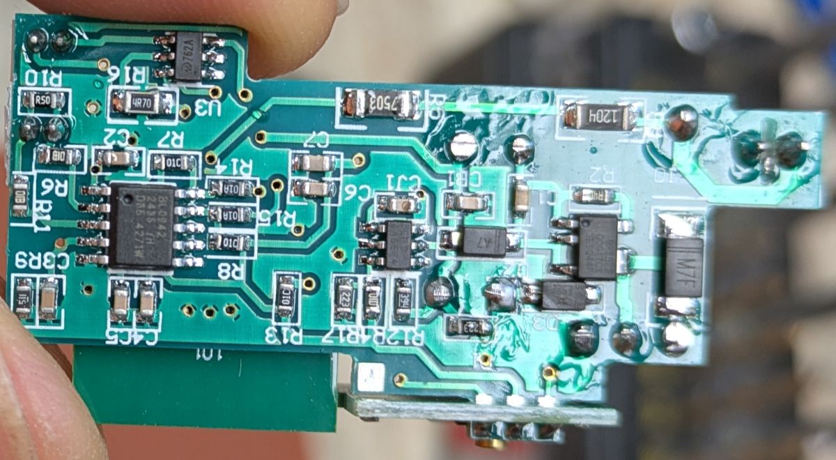
The EAKCB-EWE-M provides a BL0942 chip for energy monitoring. Here's pictures of the other chips on the back side of the main circuit board. You can read the markings for just about every chip in one photo or the other.


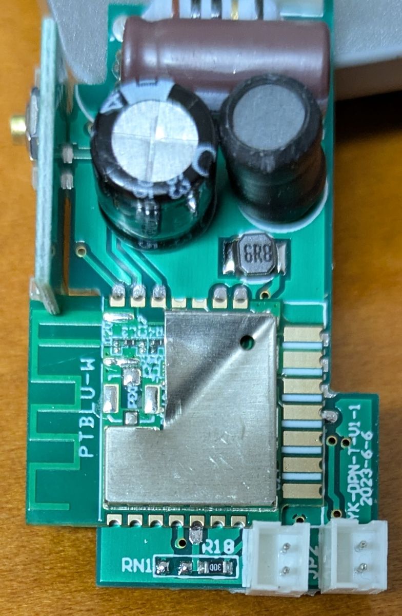
To inspect the PTBLU-W wifi module, you can bend one corner of the metal shield, but the only thing to see is the BL602 chip marking (but barely visible). To do more investigation, it is necessary to remove the metal shield. If you don't have a hot air gun, you can (permanently) remove the metal shielding with a pair of pliers.


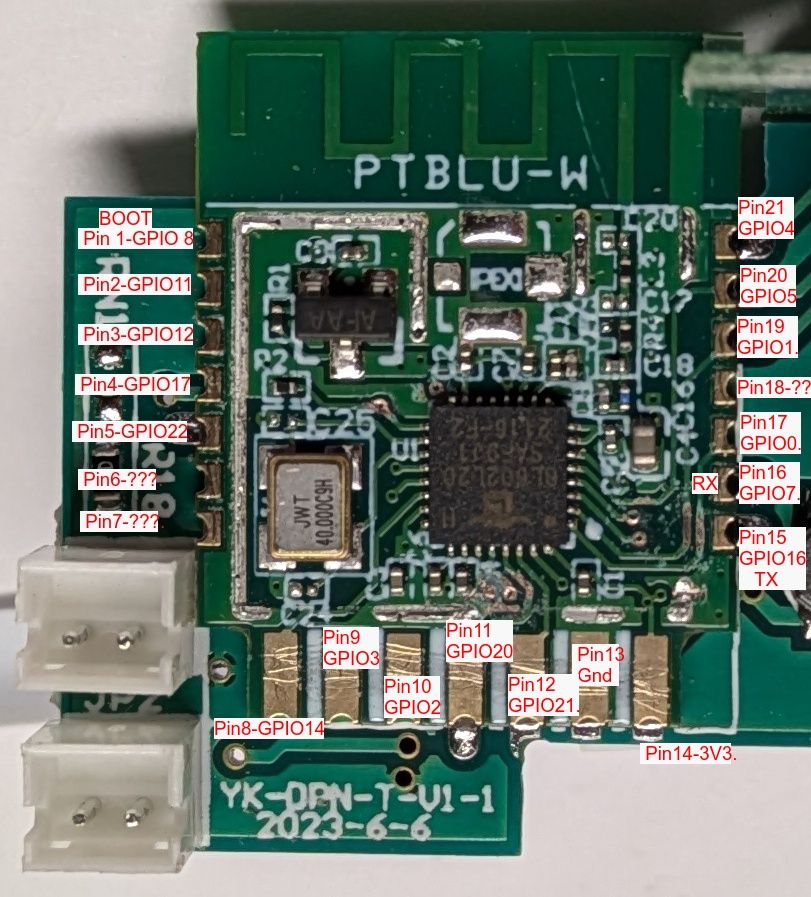
With some work, it was possible to trace the connection for every GPIO pin for the BL602. The photo below shows the GPIOs for the 21 pins of the wifi module. There seem to be 3 extra module pins. I don't have a hot-air tool to remove the wifi module so I wasn't able to inspect or test the backside of the module.


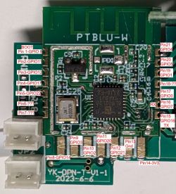
The main circuit board only uses 10 of the wifi module pins 5, 11, 12, 13, 14, 15, 16, 19, 20, 21. These are enough to control all the functions of the EAKCB-EWE-M, plus one extra pin that I don't know the function (pin 5 - GPIO 22). The wifi pin mapping is:
Pin 14 = 3V3
Pin 13 = Gnd
Pin 19 = Red LED, relay On/Off (active low) = GPIO 1
Pin 20 = Blue LED, wifi status (active low) = GPIO 5
Pin 21 = Push button switch (On/Off, active low ) = GPIO 4
Pin 11, 12 = Bi-stable relay control = GPIO 20 (Set pulse) and GPIO 21 (Reset pulse)
Pin 15, 16 = UART TX/RX connecting to BL0942 energy monitoring (GPIO 16, GPIO 7)
Pin 5 = ??? 200K ohm resistor to 3V3 ??? (GPIO 22)

There's an forum posting on how to configure the bi-stable relay in OpenBK; you may have to search further to get all the details for using BridgeFWD and BridgeREV.
https://github.com/openshwprojects/OpenBK7231T_App/issues/667

Note that you need to browse to 192.168.169.1 to access the starting OpenBK web page when the BL602 is in AP mode (with other chips, the starting web page is 192.168.4.1).

There's another posting about issues with OpenBK releases >=1.18.95 for the BL602 when activating the UART too soon after booting; a 10 second delay is recommended in the posting. https://www.elektroda.com/rtvforum/topic4127126.html

Please add to that last posting if you find other devices using the PTBLU-W wifi module, or find a simpler solution to activating the UART on a BL602.

MANY THANKS to everyone for their super-quick replies and support for this newbie! :-)

About Author
ProfAnderson wrote 18 posts with rating 10 , helped 2 times. Been with us since 2025 year.

Comments

szymon122 05 Jul 2025 22:13

What in this module acts as a current measurement? [Read more]

p.kaczmarek2 05 Jul 2025 23:52

This information is already included in the description - BL0942 connected via UART. Classic. I have also seen it connected via SPI to the CBU a few times, but much less often. In addition to the BL0942,... [Read more]

p.kaczmarek2 07 Jul 2025 03:43

@profanderson can you also post template as full JSON text from the Web App? [Read more]

ProfAnderson 07 Jul 2025 19:15

Below is the template I'm currently using. Please note that I've decided to use the scripting method to toggle the bi-stable relay rather than use BridgeFWD + BridgeREV pin roles. P.S. The LED for power... [Read more]

p.kaczmarek2 07 Jul 2025 19:20

This script will work, but I suggest you to move to channels. Declare dummy channels, like channel 2 and 3, and use setChannel 2 1 or 0, etc. This is because setting pin role will save it to flash,... [Read more]

ProfAnderson 07 Jul 2025 19:24

Ahh yes! That's an excellent tip. :-) I'll rewrite the script today or tomorrow and post it here. [Read more]

szymon122 10 Jul 2025 11:57

. I have defined the question a bit badly. Does the 63A go through a measurement resistor? A current transformer? That's a bit more than the 16A found in sockets that measure energy consumption. [Read more]

ProfAnderson 10 Jul 2025 14:50

The 63A goes through a current transformer. Also, other parts in the current path are very solid and heavy. I think there should be no problem carrying 40A without any heating. Going to 50A or 63A might... [Read more]

p.kaczmarek2 10 Jul 2025 16:10

In the picture I see two two-pin connectors, probably one is from the relay and the other is from the current transformer. [Read more]

ProfAnderson 10 Jul 2025 22:42

I've added another picture in the original description (just after "The rest of the construction looks very solid and easily capable of handling 60 amps.") It shows two 2-pin connectors on the left side,... [Read more]

divadiow 03 Sep 2025 22:14

@profanderson is this still the correct template? re https://github.com/OpenBekenIOT/webapp/pull/220 [Read more]

yuriart57 02 Apr 2026 17:23

How can I change the script so that the red LED lights up when the relay turns on? [Read more]

max4elektroda 03 Apr 2026 09:39

I would simply change the "LED" on pin 1 to "LED_n" then it should follow channel 0 (or whatever your channel for the relay is) Added after 1 [hours] 3 [minutes]: Btw: did you use the script from... [Read more]

IronReiker 03 Apr 2026 21:05

To start the energy measurement correctly, use the "command": "backlog delay_s 10; startDriver BL0942;", otherwise, the device will get stuck in a boot loop [Read more]

p.kaczmarek2 04 Apr 2026 09:21

Is this a device-specific issue or is it a generic problem on BL602? @divadiow can you check? [Read more]

IronReiker 04 Apr 2026 09:33

I have a few more of the same devices to modify, so I can’t confirm whether this is a bl602 issue. [Read more]

p.kaczmarek2 04 Apr 2026 09:36

What's the boot log of the crash? [Read more]

divadiow 04 Apr 2026 15:20

don't see a crash log, just freeze then eventual reboot custom 0x0 flash init 0 Boot2 start:Feb 1 2024,15:45:16 Group=1,CPU Count=1 ver:6.6.2 user_fw Active PT:0,Age 0 MFG not found entry... [Read more]

p.kaczmarek2 04 Apr 2026 16:03

We could manually delay it but it would be just a work around. Or maybe split auto drivers start into separate function and manually delay it on BL602? [Read more]

FAQ

TL;DR: For OpenBK users modding the 63A EARU EAKCB-EWE-M, "never be powered by mains voltage" while probing the board. This FAQ maps 10 active PTBLU-W pins, identifies the BL602 and BL0942 links, and shows how to handle the bi-stable relay and BL602 AP address safely during teardown and setup. [#21598413]

Why it matters: This thread solves the two hardest problems on this breaker: safe hardware inspection and reliable OpenBK control of a BL602-based latching relay.

Option How it works here Main advantage Main risk
BridgeFWD + BridgeREV Mentioned as supported for the bi-stable relay Native role-based setup Needs extra digging for full details
OpenBK scripting with SetPinRole Works on GPIO20/GPIO21 pulses Fast proof of concept Repeated role writes can wear flash
OpenBK channels Recommended replacement for repeated role changes Avoids unnecessary flash writes Requires script rewrite

Key insight: The PTBLU-W module uses a BL602, but the breaker only needs 10 of its module pins. The real reliability issue is not pin count; it is safe probing on a non-isolated supply and avoiding flash wear when pulsing the bi-stable relay.

Quick Facts

  • The enclosure is held by 6 rivets, and the breaker is sold as 63A, while the relay itself is marked 60A max. [#21598413]
  • The PTBLU-W sits on a board marked YK-DPN-T-V1-1 dated 2023-6-6, and the traced module exposes 21 pins, with 10 pins used by the main board. [#21598413]
  • OpenBK on this BL602 starts in AP mode at 192.168.169.1, not the more common 192.168.4.1 used on other chips. [#21598413]
  • Energy metering uses a BL0942 linked by UART to the BL602 through module pins 15 and 16. [#21598413]
  • The power path uses a current transformer, not a shunt, and the right-side connector carries mains such as 240V. [#21602862]

How do I safely open the EARU EAKCB-EWE-M smart circuit breaker and inspect the PTBLU-W WiFi module without damaging the case or shield?

Open it by removing the 6 rivets, then inspect the shield carefully. 1. Drill out the rivets and lift the case. 2. Bend one shield corner first if you only need to confirm the BL602 marking. 3. Remove the shield fully with hot air, or permanently with pliers if needed. Do not power the board from mains while probing, because the supply has no transformer. [#21598413]

What is the PTBLU-W module in the EARU EAKCB-EWE-M, and how is it related to the BL602 chip?

The PTBLU-W is the breaker's Wi-Fi module, and it is built around a BL602 chip. The module is mounted on a carrier marked YK-DPN-T-V1-1 with date 2023-6-6. The shield can be bent back enough to barely see the BL602 marking, which confirmed the chip family used in this EAKCB-EWE-M unit. [#21598413]

Which pins on the PTBLU-W module are actually used in the EAKCB-EWE-M, and what does each GPIO control?

The main board uses 10 module pins: 5, 11, 12, 13, 14, 15, 16, 19, 20, and 21. Pin 14 is 3V3, pin 13 is GND, pin 19 drives the red LED and relay state on GPIO1, pin 20 drives the blue Wi-Fi LED on GPIO5, pin 21 reads the push button on GPIO4, pins 11 and 12 pulse the relay on GPIO20 and GPIO21, pins 15 and 16 carry UART for BL0942, and pin 5 is GPIO22 through a 200K ohm pull-up to 3V3. [#21598413]

Why does OpenBK on the BL602 use 192.168.169.1 in AP mode instead of the usual 192.168.4.1?

On this BL602 device, OpenBK starts its AP interface at 192.168.169.1. The thread states that 192.168.4.1 is the usual starting page for other chips, but not for this BL602 setup. If you cannot reach the web UI at the common address, try 192.168.169.1 first before assuming the flash failed. [#21598413]

How should I configure a bi-stable relay in OpenBK for the EARU EAKCB-EWE-M using GPIO20 and GPIO21?

Use GPIO20 for the Set pulse and GPIO21 for the Reset pulse. The posted script maps Channel0 changes to short pulses: one alias drives pin role 20 high then low, and another does the same for pin role 21. That lets the breaker toggle a latching relay without holding either line active continuously. [#21600027]

What is a bi-stable relay, and why does this circuit breaker need separate Set and Reset pulses?

A bi-stable relay is an electromechanical relay that keeps its last state without continuous coil power, using separate control actions to latch ON or OFF. This breaker uses GPIO20 as Set and GPIO21 as Reset, so OpenBK must send two different pulses instead of a single steady output. That matches the thread's pin tracing and explains why simple on/off GPIO logic is not enough here. [#21598413]

How is current measured in the 63A EARU EAKCB-EWE-M breaker—through a current transformer or a shunt resistor?

Current is measured through a current transformer, not a shunt resistor. The clarification came later in the thread when the 63A path was discussed directly. That makes sense for a higher-current breaker, because the current path can stay heavy while the measurement circuit remains isolated from the full load conductor. [#21602862]

Where are the current transformer, relay, and mains voltage connections located on the EAKCB-EWE-M main board?

The board has two 2-pin connectors on the left and one 2-pin connector on the right. The left-side pair serves the current transformer and the relay. The right-side connector carries mains voltage, for example 240V. An additional photo was added to the original post specifically to make these three connectors easier to identify. [#21603398]

What is the BL0942 energy metering chip, and how does it communicate with the BL602 in this device?

The BL0942 is the device's energy-monitoring chip, and it talks to the BL602 over UART. The traced wiring assigns module pins 15 and 16 to UART TX/RX on GPIO16 and GPIO7. A later reply also confirms that BL0942-over-UART is the expected arrangement in this breaker family. [#21598413]

BridgeFWD and BridgeREV versus OpenBK scripting for a bi-stable relay—which approach works better on the BL602?

Both approaches work, but the thread moved from BridgeFWD and BridgeREV toward custom scripting, then toward channels for better long-term behavior. The original post says BridgeFWD and BridgeREV can configure the relay, but may require more searching. The shared script works immediately on BL602, so it is simpler for first bring-up, while later advice improves its durability. [#21600027]

How can I avoid flash wear in OpenBK when controlling the EAKCB-EWE-M relay, and why are channels recommended over changing pin roles?

Avoid repeated SetPinRole writes and pulse the relay through channels instead. The expert warning in the thread is explicit: changing pin roles saves state to flash, while changing channel values does not have to. That matters if the breaker switches often, because frequent flash writes can wear storage over time. [#21600032]

What causes UART problems on BL602 devices with OpenBK releases 1.18.95 and newer, and how does the 10-second delay fix help?

The reported issue is that BL602 devices can misbehave if OpenBK activates UART too soon after boot on releases 1.18.95 and newer. The workaround is a 10-second delay before enabling UART. That delay gives startup time for stable initialization and avoids the early-boot timing problem described in the linked forum note. [#21598413]

How does the PTBLU-W BL602 module compare with the older PSF-B module used in similar smart breakers?

This unit uses PTBLU-W with a BL602, while earlier breakers were said to use a PSF-B module. The thread does not provide a full electrical comparison, but it does show one practical difference: the BL602 OpenBK AP page starts at 192.168.169.1. It also notes that internet specs for PTBLU-W were not found, so the pinout had to be traced manually. [#21598413]

What does the unknown PTBLU-W pin 5 connected through a 200K resistor to 3V3 likely do in the EAKCB-EWE-M design?

Its exact function is still unknown in this breaker. The traced fact is clear: module pin 5 is GPIO22 and connects through a 200K ohm resistor to 3V3. Because the thread found no assigned feature for it, treat it as reserved or board-specific until you verify behavior with measurements off mains power. [#21598413]

How should the OpenBeken JSON template for the EARU EAKCB-EWE-M be updated after the webapp pull request 220 changes?

The thread does not contain the updated post-pull-request-220 template, so you should treat the posted JSON as a historical baseline, not a final current template. That baseline names vendor EARU, model EAKCB-EWE-M, chip BL602, and maps pins 1, 4, 5, 20, and 21. The later question about pull request 220 appears unanswered in the provided posts. [#21652684]
Generated by the language model.
%}