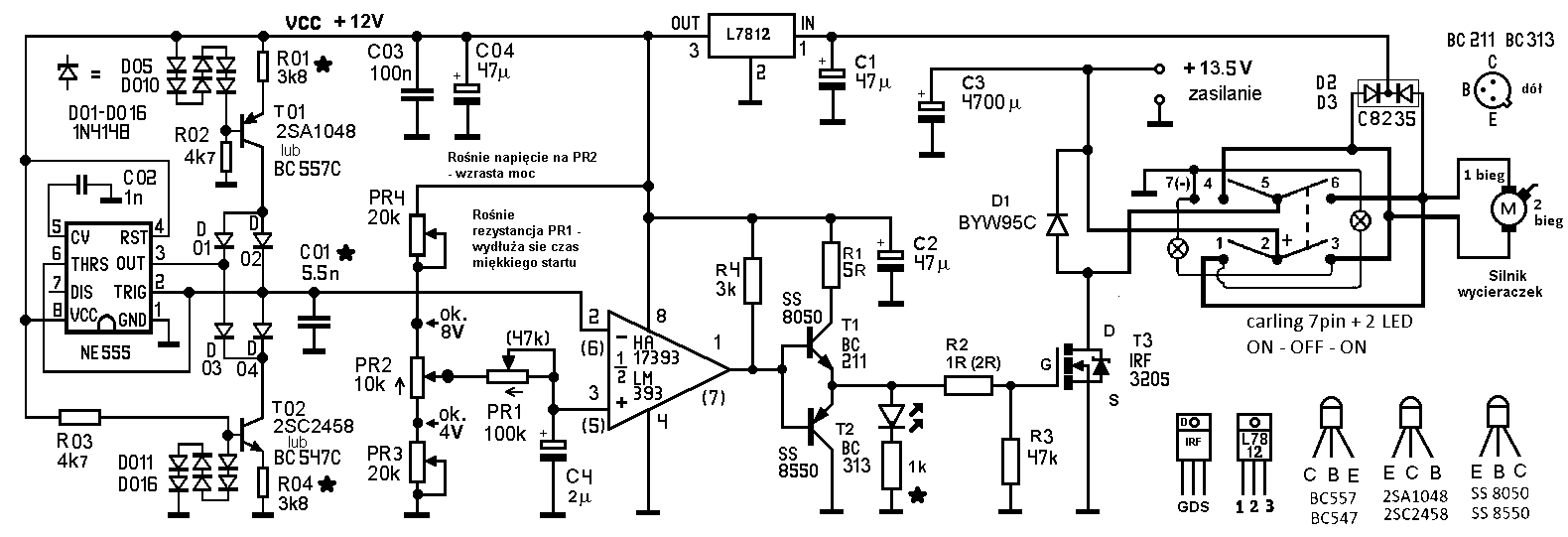
Ultrasonic PWM with soft start for speed control of a DC motor.

.
The circuit was created out of the need to smoothly regulate the speed of a VAG automotive wiper motor. The motor drives the knot toaster shaft via a 2:1 gear ratio. Previous methods using two motor speeds and two voltages from an ATX power supply (somewhat regulated) proved ineffective. The ATX power supply now has the voltage raised to 13.5V permanently. The motor is also reworked - isolated the brush from the ground and an extra wire brought out. This gave the possibility of rotation in both directions.
In the design I was keen for the system to operate beyond the limit of human hearing, so that no squeaks or whistles could be heard, as it takes about two hours to bake a knot. The regulator I made earlier for drilling into PCBs with a motor from a screwdriver on an LM358 works fine, but you can hear the sound. Fortunately, this PCB activity does not last long. The soft start is designed to eliminate jerks and to cause a slow increase in the current drawn from the power supply, as the ATX power supply's short-circuit protection circuit does not like abrupt changes.
The project came about after unsuccessful attempts to generate higher frequencies on operational amplifiers and use them as comparators. Searching the web I finally found a triangle generator solution to adopt. The generator worked immediately. I then struggled a bit with MAA741 and LM358 as comparator - they didn't work. A typical HA17393 comparator worked.
I designed the generator current sources on transistors. I decided that for my application they did not need to be very accurate and replaced the operational amplifiers in the triangle generator (link one) with transistors (any low power pair). I replaced the Zener diode with six ordinary ones because I didn't have one. The generator started and stayed that way. In general, the regulator is made from 'recycled materials', from disassembly and everything that was already there. I only bought a 10k rotary potentiometer and two precision ones of 20k each.
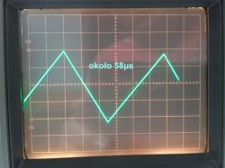
The regulator from the schematic works at about 16000 Hz. There is no noise or squeaks. A bit about the settings. PR2 is the PWM control. Using potentiometers PR3 and PR4, you can set from which speed the motor should start. The minimum I have set myself is that the motor has a low speed and is always rotating. From this speed, you can adjust up to 100 %. To set the soft-start time, potentiometer PR1 and capacitor C4 are used. (Instead of PR1 there is a 47k resistor.) For starting it is good to have an oscilloscope, but it can also succeed without one. Approximate voltages to set are given.
I am an amateur electronics technician and the text below is based on internet news.
The charging (discharging) current of capacitor C01 flowing through resistor R01 (R04) must be small to get a good signal shape, the current flowing through resistor R01 should not exceed 20 mA.
This current is calculated from the formula
I=(UD5-D10 - UBE)/R01, I=(3.6V-0.6V)/3800Ω=0.00078947A
where UD5-D10 is the voltage drop across the diodes - 3.6V(in this case 3*0.6V), and UBE is the conduction voltage at the base-emitter junction of transistor T01 (0.6V).
If the charging and discharging currents are equal then the charging and discharging times (rise and fall) can be calculated from the formula:
T=VCC*C01/3*I
The period will therefore be 2T and the frequency f=1/2T
.
I am from the generation that was taught the "only right language", so don't be surprised by the Cyrillic alphabet. I used:
https://www.radiolocman.com/shem/schematics.html?di=655279
https://www.rlocman.ru/shem/schematics.html?di=655279
http://zpostbox.ru/sawtooth_wave_generator_based_on_555_timer.html
https://www.elektroda.pl/rtvforum/topic1047137.html#5295680
The layout meets my expectations. I am posting with the hope that someone will use it. I'm not posting the circuit boards because it's a bit of a hybrid made up of two boards. The first is a triangle waveform generator on an LM555 timer. It's good, no tweaks, but it's just a 555 cube and literally a few components. The second is a soft-start PWM, now on an LM393 comparator. Previously there were trials on an MAA741 operational amplifier and an LM358. There is now an adapter in a half spider from the 741 to the 393, a few jumpers and components on either side of the board, so it doesn't make much sense. I chose to split it into 2 boards because of:
- lack of space in the chassis where the circuit has to fit,
- I didn't know if the circuit would work (I'm just an amateur and I have big deficiencies in electronic knowledge, I decided to divide the project into a generator and a PWM regulator, hoping that if the generator works, then I will deal with the PWM with soft start, on this or another schematic).
Unfortunately the last point worked out fine, I was combining on a couple of versions.
.
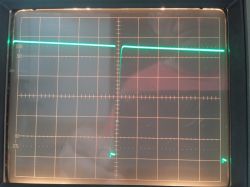
Just before maximum filling.
.
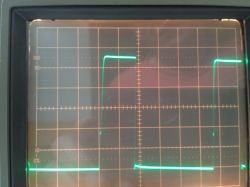
Set minimum turnover.
09. 07. 2025 r.
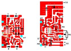
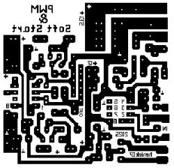
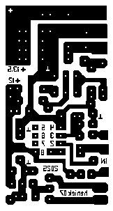
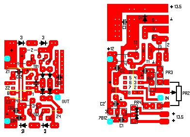
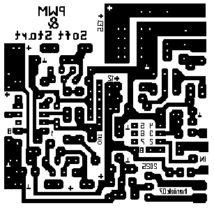
I am posting the reworked tiles, in the hope that perhaps a colleague will benefit. It is still a hybrid solution. If anyone needs to convert, please write to PW. The tiles are done in plain Paint. A long time ago I made a small project on the fly and it stayed that way. Then it was just copy paste. I know there are dedicated programs, but my penultimate board was made in 2022.
Tiles:


.
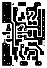
Elements on pathways:
.
10. 07. 2025 r.
Boards together, you will not need one jumper - Z3 on the triangle generator. You need to connect OUT to IN.
.


Comments
You have not taken into account that too high a frequency, will generate losses in the (steel) cores. The maximum that is used is 200 - 500 Hz. 16 kHz is the frequency of the FBT in CRT TV. [Read more]
The lack of squeak in the ears is more valuable in this application than the loss of energy. [Read more]
Hello I think it would be simpler to make a regulator using a typical PWM modulator e.g.: UC3843, or TL494. https://320volt.com/en/motorlu-bisiklet-icin-motor-surucu-devresi-tl494-pwm In this... [Read more]
Amateur to professional question: If I use a pulse capacitor of 0.1 to 1µF in parallel to the D1 diode, could it be that the motor will run at some constant voltage without dropping to zero? I saw such... [Read more]
. If you do this you will be putting short circuit pulses through T3 that are limited by this new capacitor. Bad idea. Losses will reach C*U^2*0.5*f. A low-pass filter, preferably LC, falls between the... [Read more]
Thank you. In that case, I won't be doing anything else. [Read more]
I admire that you wanted to do PWM on foot. There are so many circuits that integrate this. The UC3843 mentioned allows you to control peak current, for example. And it's very old and readily availabl... [Read more]
As I wrote. I am an amateur not a professional. My knowledge is fragmented. I don't know which components are dedicated to certain applications. What was needed was a PWM with soft start. I use the first... [Read more]
I'm afraid the squeal is there and reaching your ears, only you can't hear it. I probably wouldn't hear it either. But 16 kHz is within the range heard by humans (it's not ultrasound) and very young people... [Read more]
The 58µs period is about 17 241Hz. I'll have to bring in someone younger and ask for detection. If it bothers the youngsters I will reduce the capacitance of C01 from 5.5nF - it is put together with 3.3nF... [Read more]
. I would be afraid to meet you on the road in a snowstorm in a crackling cold :-) . The most relevant components used are of consumer standard - i.e. designed for temperatures of 0-70°C, reliable operation... [Read more]
. I understood from the author's description that, although the motor came from a car windscreen wiper, it was used for a completely different purpose: "The motor drives the shaft of the knot toaster".... [Read more]
. Such capacitors quite possibly are already inside this motor, paired with chokes. They form a low-pass filter. However, it is better to control the dips to zero on the comparator side. . Since when... [Read more]
Ha! Well, yes. mentioned briefly at the very beginning of the description, somehow it got lost in the whole size of the text. Well, there was no issue :-) . [Read more]
. I built something like this last year. Attiny85 + a couple of discrete components and two relays. Soft start (in both directions, change of direction automatically with deceleration) nothing squeaks... [Read more]
Mate ArthurAVS can you reveal, to a colleague from the same province (almost a countryman), the frequency at which your PWM operates. To me, just change the capacitance of C01 to a larger one and the... [Read more]
@heniek07 I can't remember exactly anymore, but about 10kHz on a hardware PWM. Programmatically you can probably get more like 25kHz out. Switch, button, 10k potentiometer and two relays (I didn't have... [Read more]
. Thank you! [Read more]
It uses adjustable step-down converters to regulate the speed of the DC motors, reducing the voltage. We have a full range from zero with no squeaks. Inverters for a couple/teen PLN each with a soldered... [Read more]