Interior and reverse engineering of the Ariston Velis 80 Wi-Fi electric water heater on ESP32 (part1
 .
.
What is it that a boiler with a Wi-Fi module inside offers? How is it built, what does the app offer? Can its firmware be changed? I invite you to the first part of the adventure with the Ariston Velis 80 and the Ariston NET app - today we will start with the purchase, the unpacking, the app test and present the tiles from inside. Then we'll start working on analysing the communication protocol, capture data with a logic analyser.... we'll see how much we can do.
 .
.
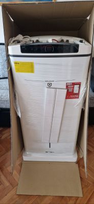
Let's start with the purchase. The hardware was bought for the house by our forum mate @DeDaMrAz , who is simultaneously developing with me our electrodes open source firmware for IoT devices. I got all the images from a colleague and we developed the theme together.
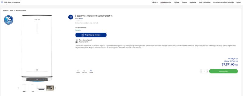
The device cost €322, but it was bought where my colleague lives, i.e. in Serbia - the price in Poland may vary.
 .
.
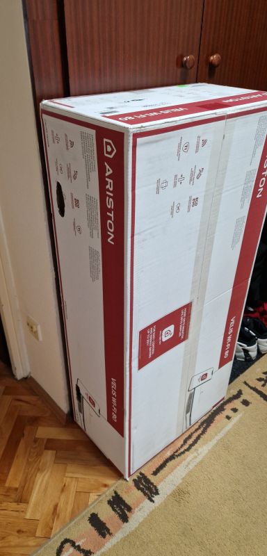
The package arrived quite quickly, the courier brought such a box:
 .
.
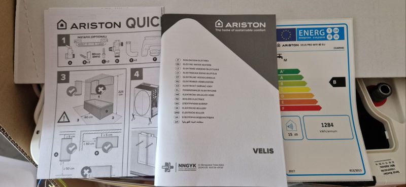
The whole thing is well packed for transport. In the box we have a full pictorial manual and a detailed multilingual manual. There is also a leaflet declaring the energy class B of the product.
 .
.
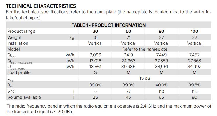
The manual is also available online. It specifies parameters such as (for the 80 version) a weight of 27 kg, a capacity of 65 litres, a noise level of 15 dB and a declared energy consumption per week of approximately 27 kWh in smart mode and 35 kWh in standard mode.
 .
.
Ariston NET App .
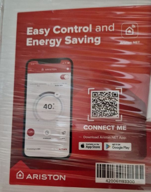
On the packaging you will find a QR code leading you to the shop of your choice - Google Play or Apple Appstore:
 .
.
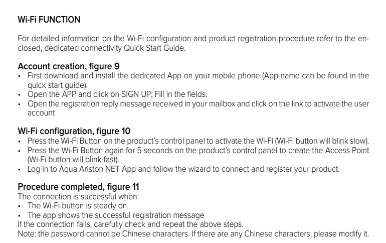
Pairing is very simple, we simply put the device into pairing mode following the instructions after registering with the app.
 .
.
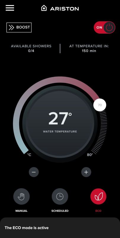
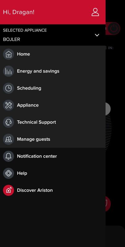
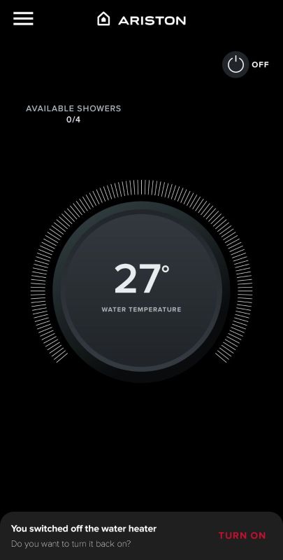
We then get access to the boiler panel, where we can edit its programme and schedule, create automation, view the current and target temperatures, check the time left to heat up and the estimated number of 'showers' its condition will allow:
 .
.
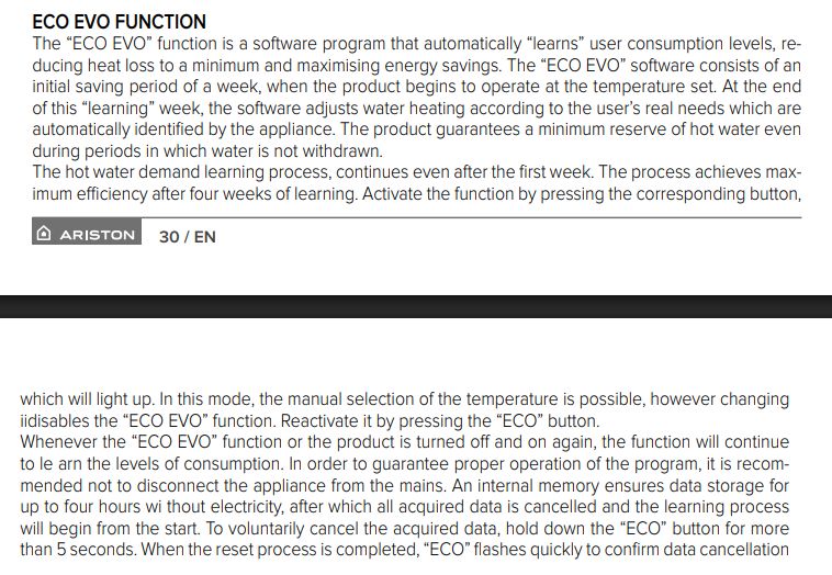
An interesting feature is the ECO option - this is based on an analysis of the user's previous habits. At first, this function "learns" for a week how we use the boiler and then adapts the heating to our habits. The aim is to reduce energy consumption and reduce heating when it is not needed.
 .
.
The learning process continues and reaches its greatest efficiency after a few weeks. At the same time, the algorithm makes sure that even in an unexpected situation, the boiler has a minimum of usable hot water.
 .
.
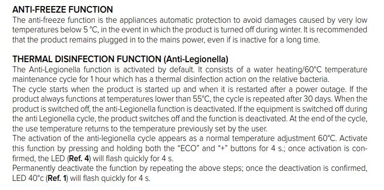
The boiler also has functions such as antifreeze, which is automatic protection against water freezing inside the unit by activating the heater when the temperature drops below 5 °C, and anti-legionella, which is a thermal disinfection cycle that heats the water to 60 °C per hour to eliminate Legionella bacteria.
Interior of the appliance .
Time to start disassembly. What does such a device control?
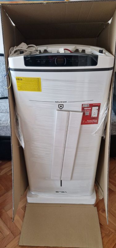 .
.
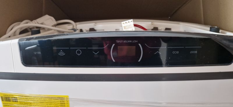
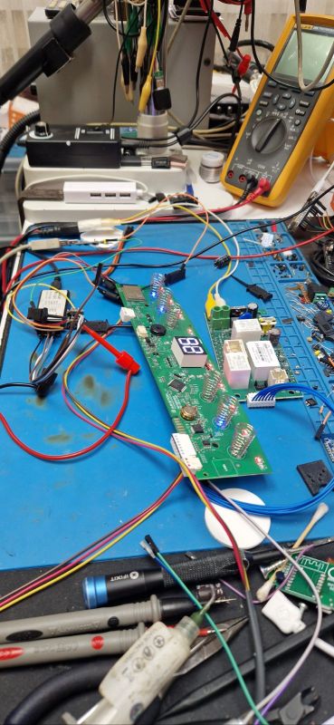
Electronics on the table during testing:
 .
.
The main panel has a 7-segment two-digit display, a Wi-Fi module with ESP32, and an additional microcontroller.
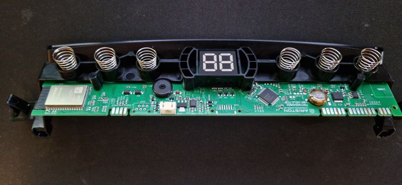 .
.
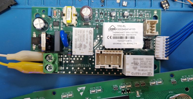
Separately, we have a power supply with relay. The power supply is based on the LNK623DG. The designation is 740190023201 TFE-RL. Interestingly, there are even interference filters and a varistor inside already. However, this is not the cheapest product from China.
 .
.
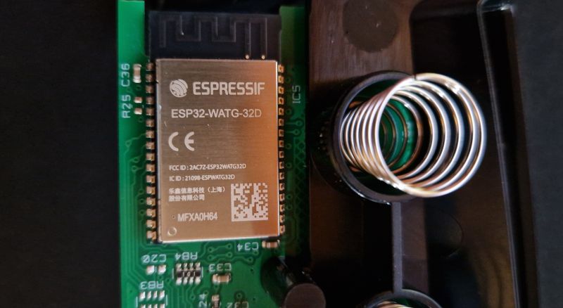
Let's focus on the Wi-Fi module. Here we have the ESP32-WATG-32D:
 .
.
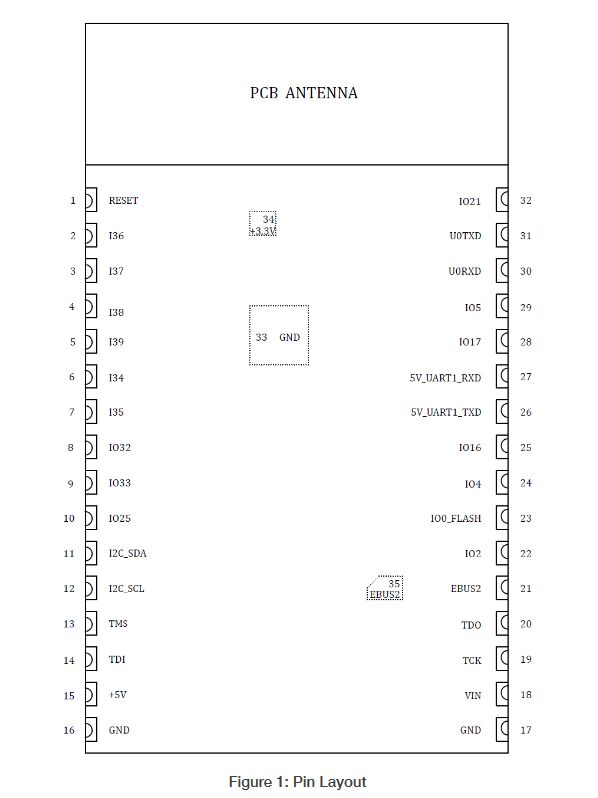
Outputs:
| Name | No. | Type | Function | ||
| RESET | 1 | I | Module enable signal (Internal pull-up by default). Active high. | ||
| I36 | 2 | I | GPIO36, ADC1_CH0, RTC_GPIO0 | ||
| I37 | 3 | I | GPIO37, ADC1_CH1, RTC_GPIO1 | ||
| I38 | 4 | I | GPIO38, ADC1_CH2, RTC_GPIO2 | ||
| I39 | 5 | I | GPIO39, ADC1_CH3, RTC_GPIO3 | ||
| I34 | 6 | I | GPIO34, ADC1_CH6, RTC_GPIO4 | ||
| I35 | 7 | I | GPIO35, ADC1_CH7, RTC_GPIO5 | ||
| IO32 | 8 | I/O | GPIO32, XTAL_32K_P (32.768 kHz crystal oscillator input), ADC1_CH4, TOUCH9, RTC_GPIO9 | ||
| IO33 | 9 | I/O | GPIO33, XTAL_32K_N (32.768 kHz crystal oscillator output), ADC1_CH5, TOUCH8, RTC_GPIO8 | ||
| IO25 | .10 | I/O | GPIO25, DAC_1, ADC2_CH8, RTC_GPIO6 | ||
| I2C_SDA | 11 | I/O | GPIO26, I2C_SDA | ||
| I2C_SCL | 12 | I | GPIO27, I2C_SCL | ||
| TMS | 13 | I/O | GPIO14, MTMS | ||
| TDI | 14 | I/O | GPIO12, MTDI | ||
| +5V | 15 | PI | 5 V power supply input | ||
| GND | 16,17 | PI | Ground | ||
| VIN | 18 | I/O | .12 V / 24 V power supply input | ||
| TCK TCK | TCK | 19 | I/O | GPIO13, MTCK | |
| TDO | |||||
| TDO | 20 | I/O | GPIO15, MTDO | ||
| EBUS2 | 21,35 | I/O | GPIO19/GPIO22, EBUS2 | ||
| IO2 | 22 | I/O | GPIO2, ADC2_CH2, TOUCH2, RTC_GPIO12, HSPIWP, HS2_DATA0 | ||
| IO0_FLASH | .23 | I/O | Download Boot: 0 SPI Boot: 1 (Default). | ||
| IO4 | 24 | I/O | GPIO4, ADC2_CH0, TOUCH0, RTC_GPIO10, HSPIHD, HS2_DATA1 | ||
| IO16 | 25 | I/O | GPIO16, HS1_DATA4 | ||
| 5V_UART1_TXD | 26 | O | GPIO23, 5V UART Data Transmit | .||
| 5V_UART1_RXD | 27 | 27 | I | GPIO18, 5V UART Data Receive | |
| IO17 | 28 | -. | GPIO17, HS1_DATA5 | ||
| IO5 | 29 | I/O | GPIO5, VSPICS0, HS1_DATA6 | ||
| U0TXD | 30 | I/O | GPIO1, U0TXD | ||
| U0RXD | U0RXD31 | I/O | GPIO3, U0RXD | ||
| IO21 | 32 | I/O | GPIO21, VSPIHD | ||
| GND | 33 | PI | EPAD, Ground | ||
| +3.3V | 34 | PO | 3.3V power supply output |
 .
.
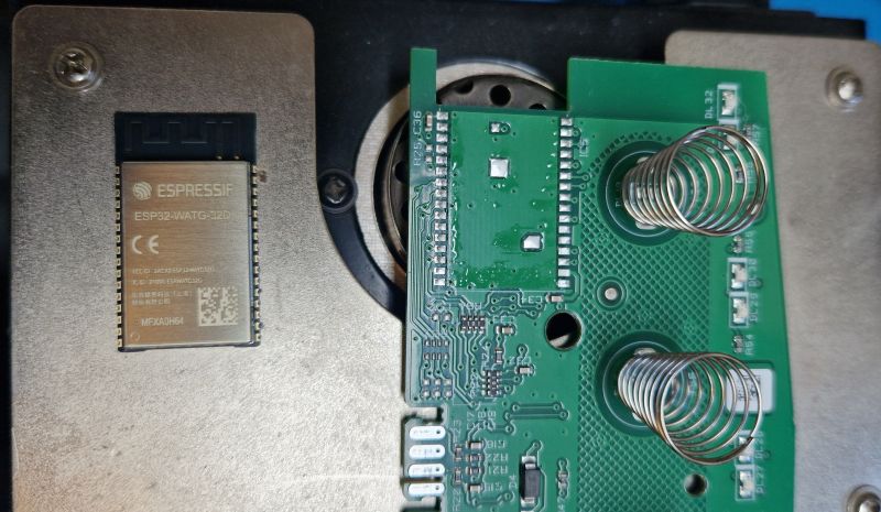
We soldered it out using flux and hot air.
 .
.
We also looked under the screen to get to the Flash memory:
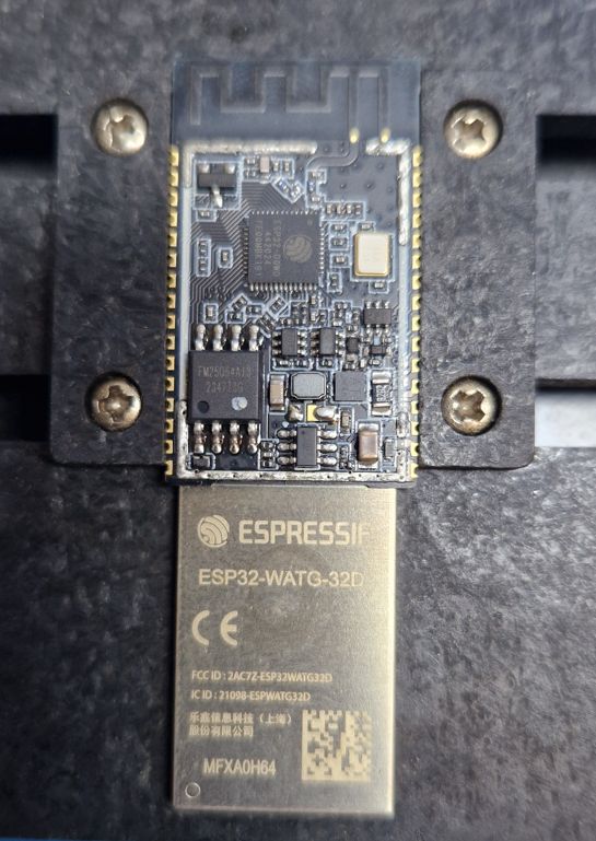 .
.
Next to the ESP is the Flash memory with SPI interface - FM25Q64A13, which is 64M-BIT. Divided by 8 gives us 8Mb.
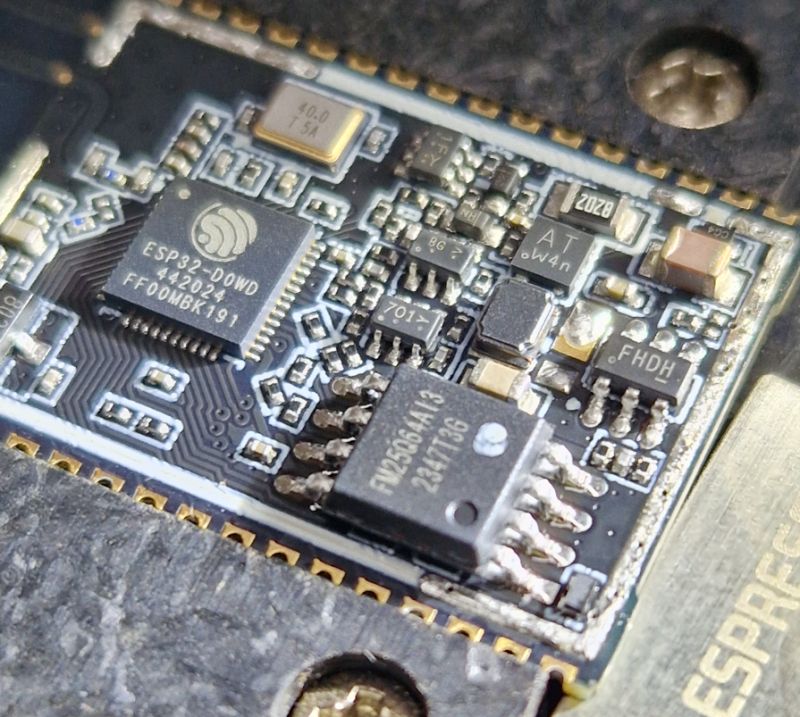 .
.
Copy of the batch (before pairing) made with esptool.py: https://github.com/openshwprojects/FlashDumps/commit/5e772e8573257f2cd69224823297cade7d9a13ba
Communication protocol analysis .
For testing we used a USB to UART converter and a logic state analyser. I have presented it before:
Reverse engineering an unknown I2C protocol with the Sigrok analyser using an LED controller as an example .
The board connected for testing:
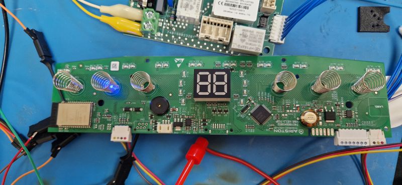
Boot log from ESP32:
  @0V@Ђ ets Jun  8 2016 00:22:57

rst:0x1 (POWERON_RESET),boot:0x13 (SPI_FAST_FLASH_BOOT)
configsip: 0, SPIWP:0xee
clk_drv:0x00,q_drv:0x00,d_drv:0x00,cs0_drv:0x00,hd_drv:0x00,wp_drv:0x00
mode:DIO, clock div:2
load:0x3fff00b8,len:2704
load:0x40078000,len:22680
load:0x40080400,len:4
ho 8 tail 4 room 4
load:0x40080404,len:2676
entry 0x4008055c
  ARES_MODULE_VERSION            02.09.10

RELOC Platform v0.0.22 (31d8388b-dirty)
flash chip id 10567703
flash size 8388608
=======================================================
[ ATG_REM4A_EWH - EARTH ]
Build timestamp: Jul  8 2024 11:14:50
FW Version     : 14.115.22"a"
HW Version     : 0.0
Author         : ATG - RELOC
Branch         : trunk
Notes          :
=======================================================
> [nvs] online
Key partition found
nvs_flash_read_security_cfg retcode(bis): 0
Reserved build encrypted OK
[reserved] online
	 flash_crypt_cnt: 7
vee encryption disabled
getting echo area!
Bus ready!
Not a lot of information here, although you can trace the SDK used and read the compile time with this.
Pairing log:
 A 1
----------HEAP-------------
Total DRAM free heap 8 NOW: 56924
Total IRAM free heap 32 NOW: 97376
---------BLOCK MEM---------
Maximum largest free block DRAM: 45056
Maximum largest free block IRAM: 45056
Malloc of appConfigHtml_Prototype_buf: 2166free heap pre xml: 56120
free heap post xml build: 51884
free heap: 50308
free heap: 56120
free heap post free appConfigXml_buf: 56120
free heap pre xml: 56120
free heap post xml build: 53380
free heap: 50228
free heap: 54544
free heap post free appConfigXml_buf: 54544
free heap pre xml: 54584
free heap post xml build: 49824
free heap: 46840
free heap: 51600
free heap post free appConfigXml_buf: 51600
[certs] online
inbuf tls len: 16717
largest free block DRAM: 27648
outbuf tls len: 16717
largest free block DRAM: 27648
ATGGetIdentTable!
inbuf tls len: 16717
largest free block DRAM: 19456
outbuf tls len: 16717
largest free block DRAM: 19456
Removed an element from log cfg
 $I Removed an element from log cfg
  r Removed an element from log cfg
   Removed an element from log cfg
   Removed an element from log cfg
   Removed an element from log cfg
   Removed an element from log cfg
    Removed an element from log cfg
    Removed an element from log cfg
    Removed an element from log cfg
    Removed an element from log cfg
  A Removed an element from log cfg
  B Removed an element from log cfg
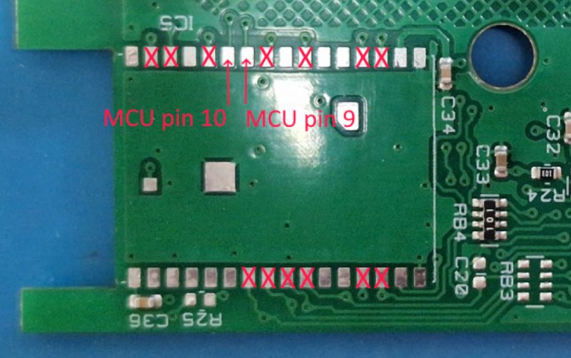
This log was received on OTXD pin 31 at baud 115200. In addition, we also have a UART to talk to the MCU, 5V_UART at 9600 baud.
 .
.
It's probably this main MCU that controls the heating, and the module from ESP32 just communicates with it. As if we knew this protocol, it would only be possible to change the ESP32 batch and so control the whole thing.
We also collected samples there:
00 3C 3C 3C 3C 3C 3C 3C 3C C3 14 24 01 00 FC 3C
C3 14 52 04 1D FE 00 13 5B 3C C3 14 25 04 01 00
01 00 02 3C C3 14 25 04 01 01 FF 01 02 3C C3 14
25 04 01 00 01 01 03 3C C3 14 25 04 00 00 01 00
01 3C C3 14 25 04 00 00 01 00 01 3C C3 14 25 04
01 00 01 01 03 3C C3 14 25 04 01 00 01 01 03 3C
C3 14 25 08 00 00 00 00 FF FF 00 00 02 3C C3 14
25 08 00 00 00 00 FF FF 00 00 02 3C C3 14 25 04
00 00 FF 00 FF 3C C3 14 25 08 00 00 00 00 FF FF
00 00 02 3C C3 14 25 08 00 00 00 00 FF FF 00 00
02 3C C3 14 25 08 20 03 8A 02 20 03 20 03 F9 3C
C3 14 25 08 BC 02 5E 01 20 03 BC 02 02 3C C3 14
25 08 32 00 00 00 C8 00 32 00 30 3C C3 14 25 08
00 00 00 80 FF 7F 00 00 02 3C C3 14 25 08 00 00
00 80 FF 7F 00 00 02 3C C3 14 25 04 00 00 FF 00
FF 3C C3 14 25 04 00 00 FF 00 FF 3C C3 14 25 04
40 05 96 2C 07 3C C3 14 25 04 01 00 FF FF FF 3C
C3 14 25 08 00 00 00 80 FF 7F 00 00 02 3C C3 14
25 04 00 00 01 00 01 3C C3 14 25 04 00 00 01 00
The same can be previewed in Pulse View. Let's connect our analyser:
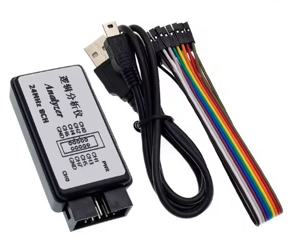 .
.
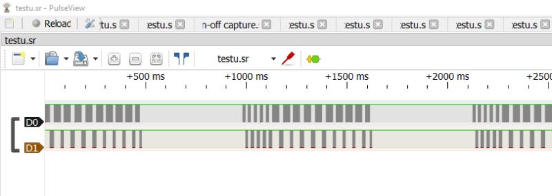
First we capture the signals:
 .
.
You can see groups of transactions here, let's zoom in:
 .
.
You can also see the individual bits:
 .
.
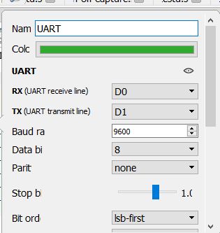
Then we add the UART decoder:
 .
.
The UART decoder allows us to easily apply bytes to the waveforms. We can then also see the transactions taking place.
 .
.
But in fact, even without Saleae you can quickly distinguish the frames. This can be seen from the repeated packet headers:
C3 41 23 0C 45 DC 4A DC 4B DC 4C DC 4D DC C0 F2 A4
C3 41 23 0C C2 F9 C3 F9 C4 F9 C5 F9 41 FA D1 40 71
C3 41 23 0C DE 40 DF 40 DD 40 DC 40 DB 40 DA 40 DE
C3 41 23 0C C7 9C C8 9C 18 45 D1 3D CF 3D C0 F9 2A
C3 41 23 0C 7F FE B0 42 C3 F0 DD 9A D4 3D D9 3E F4
C3 41 23 06 D0 3D D2 3D C4 3E 4B
C3 41 25 02 11 23 5F
C3 41 25 02 44 24 93
C3 41 25 02 45 24 94
C3 41 25 02 46 24 95
C3 41 25 02 47 24 96

C3 41 23 0C 60 10 68 13 69 13 6A 13 6B 13 43 51 29
C3 41 23 0C D3 4B C4 4B D9 46 5E 47 CB 4B CC 4B 51
C3 41 23 0C 4F 9D 50 9D 4C 9E 4D 9E 57 D1 4A D8 2B
C3 41 23 0C 4B D8 5E D9 5F D9 6E 9E 71 9E 44 DC 00
C3 41 23 0C 45 DC 4A DC 4B DC 4C DC 4D DC C0 F2 A4
C3 41 23 0C C2 F9 C3 F9 C4 F9 C5 F9 41 FA D1 40 71
C3 41 23 0C DE 40 DF 40 DD 40 DC 40 DB 40 DA 40 DE
C3 41 23 0C C7 9C C8 9C 18 45 D1 3D CF 3D C0 F9 2A
C3 41 23 0C 7F FE B0 42 C3 F0 DD 9A D4 3D D9 3E F4
C3 41 23 06 D0 3D D2 3D C4 3E 4B
C3 41 25 02 11 23 5F
C3 41 25 02 44 24 93
C3 41 25 02 45 24 94
C3 41 25 02 46 24 95
C3 41 25 02 47 24 96
Frames written in this way also immediately allow us to search for the length of the packet - this is the fourth byte. This is not hidden in any way (for example - there is no XOR with a constant or packet ID). Count it yourself - it fits. For example, a packet with 0x02 argument still has two bytes after 0x02, and at the end probably.... CRC. The checksum is generally at the end.
This situation is also interesting:
C3 41 25 02 11 23 5F
C3 41 25 02 44 24 93
C3 41 25 02 45 24 94
C3 41 25 02 46 24 95
C3 41 25 02 47 24 96
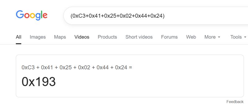
Here you can see that something is growing and the checksum is growing with it. You can try to derive this sum. 0x45 has increased by 1 and the control sum has also increased by one.... so it's probably the sum modulo 256, a quick check confirms:
 .
.
This can now be verified. PulseView allows you to write plugins, and plugins can be based on other plugins - so for example Modbus is based on UART. Documentation:
http://sigrok.org/wiki/Protocol_decoder_HOWTO
I have therefore prepared a CRC checking plugin:
Code: Python
After checking, I put the result under the decoded packet. This allows me to quickly check all communication. These plugins are really very convenient.
Code: Python
However, something went wrong. It seems that half of the packets have one byte in front, which is skipped in the CRC.

Corrected:
Code: Python
Much better:
 .
.
You can go one step further and verify the length as well. This will allow us to quickly check that I have correctly understood the meaning of the box in the frame. I compare the length from the frame field with the actual length of the frame (reduced by the header and CRC):
 .
.
Similarly, packet type information can be issued:
 .
.
I have also added a display of the data carried by the package:
 .
.
Now you can move on to the next step. Consider this section:
 .
.
It looks like packet 0x25 could be a kind of value reading.
Here we have:
- a query of what is at address 11 23
- answer that 00 00 01 00
- a query about address 44 24
- reply, DC 05 C8 00 B8 0B DC 05
- request for address 45 24
- answer DC 05 00 00 B8 0B E8 03
- request for address 46 24
- reply 64 00 32 00 B8 0B 64 00
- request for address 47 24
- reply 0A 00 01 00 64 00 0A 00
Then packets 0x25 end and 0x23 begin:
 .
.
Let's go back to 0x23. It looks like the addresses are consecutive - 0x4424, 0x4524, 0x4624. In that case, one could bet that the first is a less significant byte, and in practice we have here 0x2444, 0x2445, etc.
This excerpt also confirms this - 00 00 01 00 - this is simply 1.
Then what do we have here?
DC 05 C8 00 B8 0B DC 05 .
DC 05 -> 05DC -> 1500
C8 00 -> 00C8 -> 200
B8 0B -> 0BB8 -> 3000
DC 05 -> 05DC -> 1500
I wonder what the values are - hours? But that may come later.
It's now still the 0x23 package:
 .
.
Z - query, O - answer.
Z: 60 10 68 13 69 13 6A 13 6B 13 43 51
O: 24 01 23 01 26 01 23 01 25 01 FF FF
Z: D3 4B C4 4B D9 46 5E 47 CB 4B CC 4B
O: 00 00 00 00 00 1B 00
Z: 4F 9D 50 9D 4C 9E 4D 9E 57 D1 4A D8
O: C9 00 00 00 00 00 00 00 00 00 00
Next:
Z: D0 3D D2 3D C4 3E
O: 00 00 00
At this point I'm puzzled by the change in response length with the same query length. I thought these were setting records, but it's hard to tell at this point.
Full PulseView plugin code for review .
This should be placed in C:³³³³ Program Files (x86)³³³³ PulseView³share³libsigrokdecode³decoders³art_exporter as pd.py with the appropriate call from init. If in doubt, just look at other decoders, e.g. Modbus.
Code: Python
Further plans .
For the second part of the topic:
- collect more data
- start comparing data from the packages with that from the application
- try to collect data when the boiler is switched on and off, compare, find what turns it on/off
- similarly for different temperatures
- upload your own batch to the ESP and try to send something
- or upload the batch from the ESP to our ESP and try to imitate the boiler with our own program
Summary .
Decoding the protocol is not complete, but the topic got quite long, so I will split it into two parts.
Does anyone know more what this protocol might be? .
Ultimately we would like to run this boiler with its own firmware and control it from Home Assistant. The number of packages is quite large, but maybe you don't need to handle all of them to gain temperature control.
I attach the captured data. You can download PulseView, add my plugin there and view the frames. Ideas?


Comments
If I remember the service diagrams correctly this tank has two heaters and two temperature sensors. I hope this helps something. [Read more]
Just to visualize some data l parsed them in a table to get some sense and try to understand the protocol. https://obrazki.elektroda.pl/8199614300_1760276073_thumb.jpg Also If anybody is willing... [Read more]
Soon it will not be possible to run the flush toilet without a smartphone and wi-fi. Form over substance. [Read more]
@wladziowek more specifically without the cloud - well that's where we come in. This is why we work out such devices, so that they can be run 100% locally, without the cloud and without the manufacturer's... [Read more]
. For me, 100% local is simply manually enabling and setting a parameter. No water features or any other quirks. [Read more]
@wladziowek Our goal is to actually own what we buy and not rely on manufacturers "cloud" or application - remember there is no "cloud" it's just somebody else's computer 😉 [Read more]
@wladziowek in this game, however, we are concerned with getting this WiFi module to work somehow, but with open software, without reporting to the manufacturer's servers. If you want a unit without WiFi... [Read more]
And here you are absolutely right, everyone is allowed to choose what better suits their needs. I, however, of old, prefer what I wrote :) . And I am not imposing anything on anyone. [Read more]
And the problem with today's IoT hardware is precisely that manufacturers are nevertheless imposing their closed-source applications and standards on us a bit. For this reason, we are just creating open... [Read more]
"flash_crypt_cnt: 7" - means that the flash is encrypted and probably the module has a blocked re-flash via the UART. You will have to buy a new module to experiment with your own code. [Read more]
Good point. I wonder if you can get an ESP32-WATG-32D easily. And if not then just solder a QFN - not a problem for us. I've already soldered QFN myself to reprogram the T34 (such a WiFi module - BK7231N... [Read more]
The problem is that your work will be a curiosity (although I'm rooting for it!) - not many people will use it because it's not straightforward to solder an ESP32, and somehow I don't see these modules... [Read more]
. If the module is big enough, an adapter for another one can be made. [Read more]
Module is used strictly for communicating, none of the pins are actually routed anywhere else but to the test points on the back of the board. The only problem is that this particular module has 5V UART... [Read more]
what was the read back of esptool get-security-info against the ESP32? [Read more]
I have a similar one only without WiFi - I wonder if it would be possible to mount such a module on an ESP32. . And where can one find such service manuals? I need to look inside to assess the condition... [Read more]
. Do you have room for this ESP module, or a completely different board? [Read more]
. I'll check. I have to look in there anyway to get the heaters and see what condition they are in. When I get there I'll take pictures - maybe I can upgrade something by adding WiFi and accurate temperature... [Read more]
. https://manuals.plus/pl/ariston/velis-evo-wi-fi-80-electric-water-heaters-manual#installation_scheme https://library.ariston.co.uk/velis-evo-uk-manual/65441707 Once at some training I was looking... [Read more]