logo elektroda
logo elektroda
X
logo elektroda

Flashing OpenBeken on EZAIoT Wifi RF Thermostat for Local Control

groove6j 1632 52
ADVERTISEMENT
  • Helpful post
    #1 21441997
    groove6j
    Level 8  
    There is one Tuya cloud device remaining at my home, and it is my thermostat. T9W 2.0 R9BW 2.0 (by EZAIOT, but possibly there are different "vendors" like SALCAR or others). Sold by the big Chinese market. It can't be controlled by LocalTuya (because of some weird protocol version), only cloud.
    My target is to make it locally controllable by flashing OpenBeken on it. I don't yet know what the chip is inside, but it seems to be at the room thermostat part. Also seems to be a TuyaMCU device (I extracted tons of dpIDs from iot.tuya.com portal, also there is a non-WiFi model which could be missing the WiFi chip entirely).

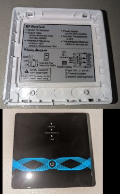
    It consists of 2 parts -
    * RF receiver part which is powered by mains power. RT-RC9PLUS 1.1_PCB v1.0 200100164
    * room thermostat with LCD screen, setting knob and WiFi, powers either by 2x AA 1.5v batteries or USB-C (or both)
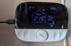
    EZAIOT room thermostat with an LCD screen displaying a temperature of 21.9°C.
    The image shows the back panel of an RF receiver and the front of a room thermostat.

    RF receivers board in the picture below. There seems to be RF receiving part, relays, status LEDs, contacts COM, OPEN, CLOSE and power input. Pairing switch and some 20pin chip which has no initials on it. Doesn't seem to be any smart device, only RF receiver.
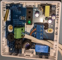
    Open RF receiver case with visible electronic components, LED, and connectors.

    More will follow!

    Added after 1 [hours] 2 [minutes]:

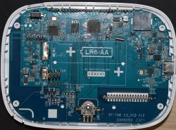
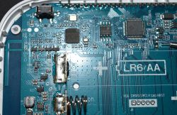
    The thermostat board looks like this:
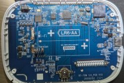
    Circuit board with integrated circuits, battery springs, and connectors.

    On the other side is the LCD screen and not much else. The main WiFi chip looks to be the 48pin chip to the left. Is it some ESP32 variant? ESP-WROOM-03 perhaps? The board config looks similar to that. I also read the progress you are doing with OpenESP! Great work!
    Then there is BAT32G127GH 232101T, which looks to be some kind of LCD controller/MCU. Then there is some unmarked 8pin chip.
    Also 48pin LGA chip and 8pin SOIC chips have their labels removed and 123456789 can be seen printed on them.
    Any thoughts?
    Also there are 2 serial ports, one marked "LOG" and another to the right of it. And some pins (VDD,SWDIO,SWCLK,GND,NRST) right on the bottom of the battery place.

    Got this from the serial port called LOG:
    
    [MEM DBG] heap init-------size:256000 addr:0x1003a740---------
    #interface 0 is initialized
    interface 1 is initialized
    
    Initializing WIFI ...
    WIFI initialized
    
    init_thread(58), Available heap 0x17f8b18:12:15 INFO  tuya_iot_com_api.c:148: rst_reason is 0
    OFFSET = 97d
    GAIN_DIV = 2ad6
    18:12:15 INFO  tuya_module_demo.c:1227: thermostat_radiator:1.0.6
    18:12:15 INFO  tuya_module_demo.c:1228: firmware compiled at Jun 17 2023 12:06:23
    18:12:15 INFO  simple_flash.c:670: init succ
    18:12:15 INFO  mf_test.c:139: have actived over 15 min, not enter mf_init
    18:12:15 INFO  tuya_main.c:142: mf_init succ
    18:12:15 INFO  tuya_main.c:143: firmware compiled at Jun 17 2023 12:06:23
    18:12:15 INFO  tuya_module_demo.c:1056: product_info = {"p":"eaacu1av8nz9qdva","v":"2.0.11","c":0,"t":0}y
    18:12:15 INFO  tuya_module_demo.c:1307: pid = eaacu1av8nz9qdva, ver = 2.0.11, wifi_set_mode = 0
    18:12:15 INFO  tuya_iot_com_api.c:954: country_code =
    18:12:15 INFO  tuya_iot_com_api.c:958: MAC[1c-90-ff-16-2f-63]
    wifi_set_lps_smartps:2
    [tuya_module_demo.c:1157] sleep_time_ms = 1000
    [tuya_module_demo.c:1169] wifi is not set for powersave, don't do everything
    [tuya_module_demo.c:1157] sleep_time_ms = 30000
    18:12:15 INFO  tuya_iot.c:577: tuya_iot_init
    18:12:15 INFO  tuya_endpoint.c:234: endpoint_mgr.region:EU
    18:12:15 INFO  tuya_endpoint.c:235: endpoint_mgr.regist_key:36F7
    18:12:15 INFO  tuya_endpoint.c:210: Host region:EU
    02:00:00 INFO  lpmgr.c:148: min_dtim = 0
    02:00:00 INFO  netmgr_api.c:433: netmgr_start


    Using the other serial port - nothing yet, only some garbage data. I haven't tried reading it as ESP32 yet, I need to understand how to do that :D , and how to free up the TX/RX pins, and which to short to ground for bootmode of the chip. I have less experience with ESP
  • ADVERTISEMENT
  • Helpful post
    #2 21442788
    p.kaczmarek2
    Moderator Smart Home
    OBK supports ESP32, so we can try, and it's indeed a very interesting device you've found. Thank you for sharing.

    For ESP, you just ground IO0 at reboot time and then use esptool.py, first do read.and make sure it worked, so you have a backup.

    Maybe there is a chance that read will work without cutting traces, if not, well... you'll have to locate where RX/TX lines to MCU are.

    I see you also did dpID extraction according to our guide, it's a good start.
    https://www.elektroda.com/rtvforum/topic4021129.html
    Helpful post? Buy me a coffee.
  • #3 21442797
    insmod
    Level 25  
    While OBK supports ESP32, i haven't managed to make UART work properly.
    But, this device is some realtek according to log. Which chip exactly is unknown to me, the log is incomplete.
    And flashing would probably be problematic, i don't see any strapping pin on board. Is this a flash chip between 2 mcus? Doesn't look like it, but if you have ch341a and soic clip, you can try to take a backup
  • #4 21442798
    p.kaczmarek2
    Moderator Smart Home
    I can't see the marking on the IC clearly, can you take a better photo?
    Helpful post? Buy me a coffee.
  • Helpful post
    #5 21442801
    insmod
    Level 25  
    If the soic8 is indeed a flash chip, then is probably a RTL8720DN chip. Which is problematic, since there is no support for it yet. But, adding support for it is currently in my plans.
    Can your device see 5ghz networks from stock app?
  • ADVERTISEMENT
  • Helpful post
    #6 21442803
    p.kaczmarek2
    Moderator Smart Home
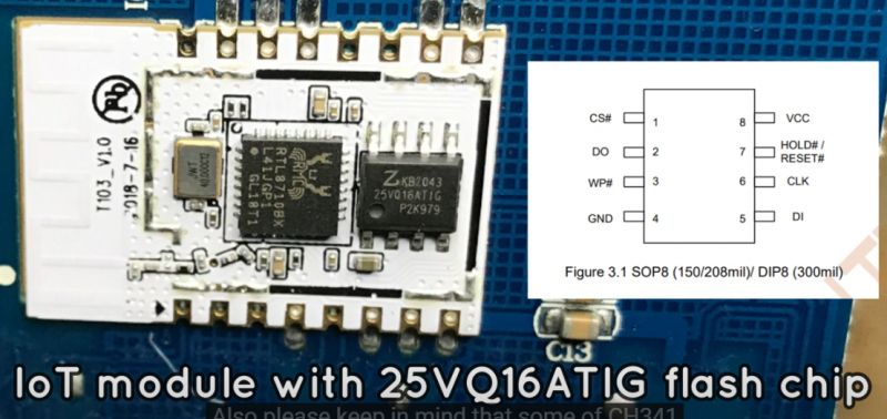
    There is at least one more Realtek with external flash chip. I saw it when making CH341 video:
    https://www.youtube.com/watch?v=z9uLPo9QAY8&t=81s
    IoT module with 25VQ16ATIG flash chip on a circuit board with a connection diagram.
    RTL8710BX + 25VQ16ATIG
    Helpful post? Buy me a coffee.
  • ADVERTISEMENT
  • Helpful post
    #7 21442813
    insmod
    Level 25  
    >>21442803 I don't believe i've ever seen AmebaZ in QFP48 format. I also tried to google AmebaZ2 family chips, but seen only QFP40/QFP32. I doubt Ameba1 are still used, so that leaves AmebaD.
  • #8 21442902
    groove6j
    Level 8  
    insmod wrote:
    but if you have ch341a and soic clip, you can try to take a backup

    I have a few eeprom/flash programmers. I just need to know what kind of flash it could possibly be, then I can try to read it.
    p.kaczmarek2 wrote:
    I can't see the marking on the IC clearly, can you take a better photo?

    I will take some pictures later with a better camera, but both soic8 chip and the 48pin chip have their markings erased and replaced with numbers 12345678. The Chinese have tried to hide what these chips are. Also there is a chip on the right (possibly RF receiver), which also has the markings erased.
    But yeah, I'll take a better picture, then post it here.

    insmod wrote:
    Can your device see 5ghz networks from stock app?

    From the log I suppose there might be 2 WLAN interfaces by the first lines. The Tuya app? How can I check? By trying to re-pair the device to a 5ghz AP?

    Anyways thanks for your interactions, this is indeed quite a specific device. After some googling I found out that some of these thermostats indeed come with the Tuya WBR3D Realtek RTL8720DN chip, which is indeed dual band.
  • Helpful post
    #9 21442947
    insmod
    Level 25  
    >>21442902 Usually flash is about 4mb in DN devices, but in some devices it can be 8mb (like WBRG1, not DN, but same chip family).
    2 interfaces are AP and STA, so no relation to bands. Yes, try to re-pair.
    And try to take log from the moment it powers to at least when in tries to connect/starts ap mode.
    Additionally, you can try to enter flash mode, if it is indeed DN.
    Before powering it up, connect log tx to gnd, disconnect it after powered. If it starts spamming to uart (same symbol at 921600 baud, not sure if i remember it correct), then it is DN chip.
    To dump via uart, download https://github.com/pvvx/pvvx.github.io/blob/master/RSH-GW018_DM/bin/wbrg1.zip, unpack it and run
    python3 rtltool.py -p COMx -b1500000 rf 0 0x400000 ff1.bin

    And to be sure
    python3 rtltool.py -p COMx -b1500000 rf 0 0x800000 ff2.bin

    I don't recommend to share backup yet, because you would still need to run original firmware, at least until openbeken is ported.
  • #10 21443456
    groove6j
    Level 8  
    insmod wrote:
    Usually flash is about 4mb in DN devices, but in some devices it can be 8mb

    You mean the SOIC8 flash or the integrated flash in the chip? When entering flash mode which flash is read? Or maybe both are used? Sorry, I haven't learned about these chips much yet. It would even be easier for me to read the SOIC flash by clip or by desoldering.

    I also wonder what purpose there is for the Realtek MCU. I hope RF transmitting and RF pairing is done within the other MCU and Realtek chip only does the data receiving from the MCU and does the WiFi part.
    In the other case, it might be difficult to reprogram pairing stuff etc... That sounds pretty problematic for me :D

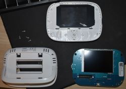
    And I took some better pictures. Maybe it will be easier to determine the chips.
    Disassembled T9W thermostat with visible internal components.
    Printed circuit board with various electronic components, including a space for LR6 AA batteries.
    Image of a circuit board with visible chips and electronic components.
  • #11 21443701
    divadiow
    Level 34  
    12 legs per side? QFN48? RTL8720DN is 48...


    Table with part numbers RTL8720DN and package type QFN48.
  • #12 21443805
    groove6j
    Level 8  
    >>21443701
    Saw your post on tuya-local GitHub. I participated there with a different nickname. I'll try to dump the firmware using @insmod instructions. Assuming it is a RTL8720DN, which it now most likely is.
  • Helpful post
    #13 21443811
    divadiow
    Level 34  
    ah! cool. yeh. got me curious and I started to hunt around
  • #14 21443867
    groove6j
    Level 8  
    insmod wrote:
    If it starts spamming to uart (same symbol at 921600 baud, not sure if I remember it correct), then it is DN chip.

    Yes, it does do that. Now I'm trying to get the python script to work.
  • #17 21444049
    divadiow
    Level 34  
    getting this looping on RTL8720DN
    Code: Text
    Log in, to see the code


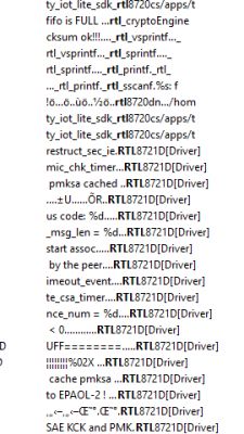
    could it be RTL8721D?
    Screenshot of system code with errors related to RTL8721D.
  • #18 21444067
    groove6j
    Level 8  
    >>21444049
    Yes, a lot of references of RTL8721D.

    This device communicates over 433MHz RF (Bidirectional FSK). I found some references to that in the dump. Wondering if this chip supports RF comms natively or relies on the other MCU.

    The flash size was 4MB, right?
  • ADVERTISEMENT
  • Helpful post
    #19 21444230
    divadiow
    Level 34  
    seems to be. cut the 8mb file in half and the two halves are identical

    Added after 29 [minutes]:

    >>21444049

    maybe not. the BW16E/RTL8720DN dev board firmware comes full of RTL8721D references too
  • #20 21552341
    groove6j
    Level 8  
    Since it is currently not possible to flash this device, I'm moving to a very simple thermostat system using one esphome relay device connected to my stove and one thermostatic device in the living room. If anyone is interested, feel free to contact me.
  • #21 21552351
    insmod
    Level 25  
    >>21552341
    Why not possible? I added support for RTL8720D about 3 months ago.
    I tested it on WBRG1 8mb, BW16 4mb and BW16 2mb, and all of them are working ok.
    GPIO and uart is fully working.
  • #22 21552775
    groove6j
    Level 8  
    >>21552351
    Sorry, I haven't followed the updates on RTL devices for a while. Great work you have done!

    About this device - we didn't really understand which variant of Realtek chip that was, because the chip's name was scraped off, only the firmware which I read was available. If I understand which variant that is, I can flash it.
  • #23 21552848
    insmod
    Level 25  
    >>21552775
    It can only be AmebaD chip, since you managed to take a backup with a tool i posted earlier.
    It wouldn't work for anything else, i even tried to use it with AmebaDplus and failed.
    OpenRTL8720D supports all AmebaD chips, that is RTL8721CSM, RTL8720DN, RTL8720DF, RTL8721DM, RTL8722DM, RTL8711TTF. Not RTL87xxDA though (AmebaDplus).
    If you flash it - it will work.
  • #24 21553039
    groove6j
    Level 8  
    >>21552848
    Trying right away!

    [size=9:d42295ab2ab]Added after 25 [minutes]:[/size:d42295ab2ab]

    >>21552848
    One more question. Should I flash with some other GUI tool I saw in the posts, or is it possible with the same python script I read firmware with?
  • #25 21553080
    insmod
    Level 25  
    >>21553039
    It's possible to flash it via script, just use wf instead of rf
  • #26 21553227
    groove6j
    Level 8  
    >>21553080
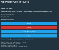
    Yes it works. I had to use the Windows tool, python script failed with wrong checksums after write.

    Configuration panel of the OpenRTL8720D device with large buttons for config, restart, and launching the web application.

    But when I disconnect my UART adapter, then it boots the stock firmware. When I connect UART, then it boots OpenRTL8720D. I can tell, because the display lights all the pixels when OpenRTL8720D is booted.
  • #27 21553231
    insmod
    Level 25  
    >>21553227
    That's strange, i haven't heard of such behaviour before.
    Just to make sure, perform OTA once to make sure both firmware slots are flashed with OBK.
    But perhaps you're wrong? This device is very likely comes with TuyaMCU, and it usually controls display.
  • #28 21553239
    groove6j
    Level 8  
    >>21553231
    Both slots are definitely not flashed. Ok, I'll try performing OTA.

    Yup - every time when the GND, TX and RX pins are connected to my FTDI adapter, it boots OpenRTL8720D, screen shows all pixels (like a screen test) and web-ui etc works.

    When it is disconnected, then temp. display works and there is no sign of OpenRTL8720D - no hotspot, no wifi connection.

    A guess now - the screen needs to be initialized somehow, maybe setting some DPids to some value? When the stock FW initializes, there are the same screen test, but after a second it initializes fully.

    update:
    OTA:

    Info:CMD:[WebApp Cmd 'loglevel 3' Result] OK
    Info:OTA:Current firmware index is 1
    Error:OTA:Get OTA header failed
    Error:OTA:OTA failed


    BTW when booting without serial adapter, it shows 02 in screen corner (it is usual behaviour), probably means that the FW2 is booted. How can I flash the other slot? I think that it boots FW1 when TX or RX is high at boot.
  • #29 21553285
    insmod
    Level 25  
    That's not how it's supposed to work.
    Btw, what image are you using for ota? I just now used that one and it worked fine: https://github.com/openshwprojects/OpenBK7231...wnload/1.18.102/OpenRTL8720D_1.18.102_ota.img
    Perhaps try to add 'startdriver tuyamcu' to either autoexec.bat or startup command

    Added after 3 [minutes]:

    And just to be sure, are you powering the board via VDD pin? If so, remove it and leave just GND and TX.
  • #30 21553289
    groove6j
    Level 8  
    insmod wrote:
    Btw, what image are you using for ota? I just now used that one and it worked fine: https://github.com/openshwprojects/OpenBK7231...wnload/1.18.102/OpenRTL8720D_1.18.102_ota.img


    I used the same file. I also tried OpenRTL8720D_1.18.101_ota.img . I tried both uploading it to webapp and pasting the link into the OTA page. Nothing - it doesn't do it at all.

    insmod wrote:
    Perhaps try to add 'startdriver tuyamcu' to either autoexec.bat or startup command

    Already did that, nothing changed.

    Added after 4 [minutes]:

    insmod wrote:
    And just to be sure, are you powering the board via VDD pin? If so, remove it and leave just GND and TX.


    Yeah, via VDD. Ok, I'll try right away.

    Added after 6 [minutes]:

    insmod wrote:
    If so, remove it and leave just GND and TX.

    Okay. It boots the stock firmware. If I connect RX too, the same.
    I can boot FW1 when I connect GND, RX, TX and VCC. (which is OpenRTL8720D)

    Update:
    OTA worked from Chrome, from Firefox it somehow didn't work. Now when booted it shows that it's FW2 in OpenRTL8720 homepage. But still the old firmware boots when I remove VCC.

Topic summary

The discussion centers on flashing OpenBeken (OpenRTL8720D) firmware onto the EZAIoT T9W 2.0 R9BW 2.0 WiFi RF thermostat to enable local control, bypassing Tuya cloud dependency. The device consists of two parts: an RF receiver (RT-RC9PLUS 1.1_PCB v1.0) powered by mains and a battery/USB-C powered room thermostat with an LCD and WiFi. The thermostat likely uses a Realtek RTL8720DN or RTL8721D chip (AmebaD family), with an external SOIC8 flash chip (~4MB). The MCU controlling the display and RF pairing is separate, possibly a BAT32G127GH or similar, hidden under the LCD with erased markings, complicating tracing and UART communication. UART lines labeled LOG provide boot logs, but the other UART intended for TuyaMCU communication shows no activity or oscillation, suggesting it may be unused or routed internally under the display. The device uses TuyaMCU protocol, possibly v0 for battery-powered devices, but attempts to sniff or communicate via UART failed. Flashing was achieved using the Windows AmebaD tool rather than Python scripts due to checksum errors. The device boots OpenRTL8720D firmware only when UART adapter is connected, otherwise boots stock firmware. OTA flashing works inconsistently, requiring proper power connections (USB-C, VDD, GND). The display initialization and MCU communication remain unclear, possibly relying on SWD (Serial Wire Debug) lines for data exchange rather than UART. The community suggests sniffing TuyaMCU traffic on UART before flashing and exploring SWD protocol analysis. Due to complexity and lack of full support for RTL8720DN chips, local control via OpenBeken is challenging but feasible with further reverse engineering. Some users have moved to simpler ESPHome-based thermostat solutions. The discussion includes detailed firmware dump and flashing procedures, chip identification challenges, and protocol analysis attempts.
Summary generated by the language model.
ADVERTISEMENT