logo elektroda
logo elektroda
X
logo elektroda

[TYWE3S-ESP8266] SM-AW713 WiFi controlled valve - interior, firmware change

p.kaczmarek2 3189 26
ADVERTISEMENT
Treść została przetłumaczona polish » english Zobacz oryginalną wersję tematu
  • Interior of the Jinvoo SM-AW713 smart valve controller with ESP8266 .
    Here I show the inside and the process of changing the firmware of a clever water/gas valve overlay that allows such a valve to be controlled via WiFi. This controller is commercially available under the name Jinvoo SM-AW713, although distributors often also give it their own designations and the version I ordered was signed as SmartLED 8073. There has already been mention on the forum of its version on BK7231, in this post , but here I will show the ESP-based version.

    Purchase of Jinvoo SM-AW713 .
    "Smart" WiFi valve controllers can be bought for as little as around £100. The price depends on where you buy. You can also buy it on our Polish auction portal, in which case you will receive the product quickly, but it is slightly more expensive.

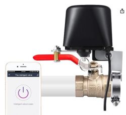
    WiFi valve controller for gas/water shown with smartphone app. .
    It should be noted at the outset that the kit you buy does not include the valve. This kit is fitted to the valve already fitted to us .
    The whole thing then looks like this:
    Diagram of an installation with a smart valve controller in a gas pipeline system. .
    Installation details:
    Valve controller with a smartphone app for valve control. .
    The whole thing can be controlled via the Tuya app, but we'll want to change that and get cloud-independent.
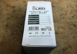
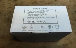
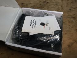
    After placing the order, we receive a box like this:
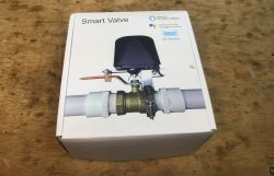
    Box of Jinvoo SM-AW713 smart WiFi valve. A white box labeled SmartLED 8073, showing a description of the WiFi water/gas valve functions. Close-up of Smart Valve box with technical specifications. .
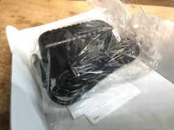
    Kit contents:
    Jinvoo SM-AW713 set in packaging Contents of the box with the Jinvoo SM-AW713 smart valve WiFi controller. Box with Jinvoo SM-AW713 valve controller set and accessories. WiFi valve controller kit, packaged in transparent plastic and a cardboard box. .
    Even the power supply is included. This is rather a plus, although I would always find one at my place already for this purpose.
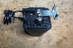
    Here is the main mechanism, the mounting parts are in the bag:

    Mounting components and the smart WiFi valve controller. .
    View of the valve overlay with a black housing and mounting mechanism on a wooden surface. .
    The case reveals to us the actual model of the device - SM-AW713, this 8073 is just the importer's designation:
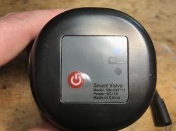
    Jinvoo SM-AW713 water/gas valve cover .
    Instructions (including a description of how to put the device into pairing mode with the Tuya app, but we don't really need that):
    WiFi smart valve installation manual Instruction leaflet of the Jinvoo SM-AW713 smart valve controller on a wooden table. .

    Interior of Jinvoo SM-AW713 .
    Remove the four screws:
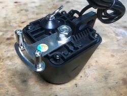
    Jinvoo SM-AW713 valve cover with mounting components. .
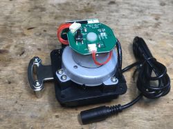
    Interior:
    Valve control module with visible PCB and wiring.
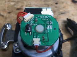
    PCB designation: SM-AW713 LED V4.0 FR-4 RoHs E364546
    Here we have two separate LEDs, one presumably for the pairing status, the other for the switching status, a pin from switching and a connector for the second board and for the motor (M+ and M-).
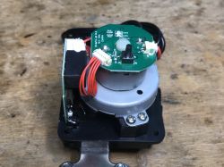
    Close-up of the internal components of the SM-AW713 smart valve controller showing the circuit board with buttons and wires. Interior of the Jinvoo SM-AW713 device showing PCB and wiring. .
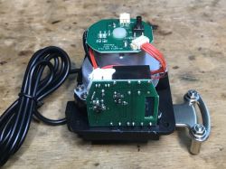
    There is a relay and a WiFi module on the second board:
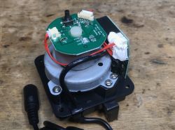
    Interior of Jinvoo SM-AW713 valve controller with visible PCB and wires. View of the interior of the Jinvoo SM-AW713 smart valve overlay with visible ESP module and wiring. .
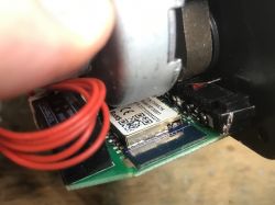
    It turns out that here is a module with ESP, so Tasmota can be uploaded:
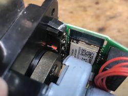
    Close-up of PCB with TYWE3S WiFi module and relay. Interior view of WiFi module with ESP8266 in valve controller. .


    Changing the Jinvoo SM-AW713 batch .
    Due to the difficult access to the WiFi module, it is worth trying tuya-convert first, which still supports some older devices. Tuya-convert allows you to change the batch via WiFi, without soldering cables. Newer ones, unfortunately, are no longer susceptible to this solution.
    The SC3-01 SmartLife switch and ESP firmware upload via WIFI (tuya-convert/OTA) .
    If, on the other hand, this method doesn't work (or we don't have the WiFi card needed to create an access point), the engine can be removed:
    Interior of the Jinvoo SM-AW713 smart valve controller with ESP8266 .
    and gain slightly better access to the WiFi module:
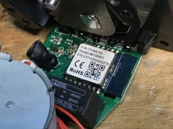
    Jinvoo SM-AW713 PCB with visible TYWE3S WiFi module. .
    By the way, here you can see the step-down converter generating 3.3V from the 12V input, this is the operating voltage of the WiFi module. Next to the IC you can also see its coil:
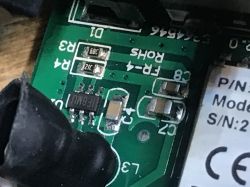
    Close-up of the Jinvoo SM-AW713 PCB with visible electronic components. .
    You can also see the transistor that controls the relay:
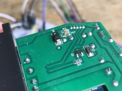
    Close-up of the PCB of the Jinvoo SM-AW713 controller with electronic components. .
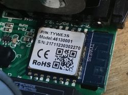
    The WiFi module itself:
    TYWE3S module on a PCB. Close-up of the TYWE3S WiFi module on a circuit board with model and serial number markings. .
    This is an ESP8266, so esptool.py will do. TYWE3S pinouts are available on the web, by the way, they are compatible with ESP12. You can read about uploading Tasmota here:
    SmartLife switch - test, interior and programming a light switch on WiFi .
    You can also use the web-based installer:
    How to install Tasmota easily - online installer tasmota.github.io/install via web browser .
    Once Tasmota has been uploaded, the template needs to be uploaded:
    {"NAME":"Jinvoo Valve","GPIO":[0,0,0,0,0,52,0,0,21,17,0,0,0],"FLAG":0,"BASE":18}
    .
    The template comes from the Blakadder website, but describing in words here we have:
    - LEDs (the first on IO5, the second on IO4)
    - button on IO12
    - relay on IO13
    The operation of this template is really very simple. Simply switching on the relay switches on the valve and vice versa. Of course, everything is done with a certain delay, which, by the way, is stated by the manufacturer itself - about 10 seconds.

    Summary .
    It turned out that on the firmware side, this gadget is really simple to drive. All you need to do is simply switch on (or off) the relay. The problem, on the other hand, is accessing the programming pads. You have to get there from the UART, unless you get lucky and the tuya-convert works.
    An additional plus is the presence of an ESP inside, although I don't know if this too at this distributor won't change in time, as even at our forum there was a post about this device in the BK version . In any case - both versions can be easily flashed and connected to HA.
    Do you see any potential practical use for such a gadget? Perhaps it could be paired with a humidity sensor, for example, and turn the water off if a leak is detected, or perhaps you would use it in some other way?

    Cool? Ranking DIY
    Helpful post? Buy me a coffee.
    About Author
    p.kaczmarek2
    Moderator Smart Home
    Offline 
    p.kaczmarek2 wrote 12026 posts with rating 10053, helped 575 times. Been with us since 2014 year.
  • ADVERTISEMENT
  • #2 20751961
    ro-x
    Level 14  
    For five (hehe) years I've been thinking of some way of turning off the water supply in the event of detecting flooding from the water sensors I have under each 'intake', such as the sink, basin, bath, washing machine or dishwasher. The same with the gas valve in the event of detection of a fire or escape of gas here or chad (thanks Satel, you have all the sensors on offer!).
    There are two problems with these types of valve turners. The first, it needs electricity to work. It needs a buffer power supply to make it reliable. The second, it needs wifi, so the whole network and server infrastructure also needs to be under a specific UPS. But what if there is a leak or a fire, when the power is out for an extended period of time, and the UPS batteries give up? Well, that's a crapshoot. Such a solution is a bit of a stopgap. It's probably better than nothing, but when it comes to safety, I don't tolerate stopgaps.
    NC solenoid valves are an alternative. These need to be powered to work. If there is no power, the water or gas will not flow. However, there are three disadvantages here. The first, they chew up a lot of electricity, which at today's electricity prices is not insignificant. The second, what if there is a fire and the electricity runs out? Well, we won't put it out. Unless, again, we use a buffer power supply. The third disadvantage is their price. A good valve costs several hundred zloty. I wouldn't put a Chinese valve for a hundred on a water or gas supply, because who knows if it will work when you need it. Or maybe it will cause the leak itself?

    So there are two ways to go about this. I will probably think about the subject for another 5 years and then make a decision :) .

    And I would only mount the described "twister" outside the house to control the watering of the garden, and only when I'm around. Because what if I'm frying on Tenerife, and the water in the garden is pouring for 2 weeks because a chinchok has failed? Valves are a serious matter though.
  • ADVERTISEMENT
  • #3 20752081
    12robert12
    Level 29  
    I've had these Chinese valves paired with flood sensors for 2 years now and it's worked superbly, they've worked more than once when the kids were going crazy in the shower 😜.
    There is control if there were offline sensors or valves,
    The risk is always that they won't work but they still provide extra security.

    In my opinion, it is important with these valves to close and open the valve once a week with a schedule - so that the valve does not stagnate, become overgrown with limescale - then the engine may not start it.

    I have after Zigbee and it works without internet automation 💪.
  • #4 20752116
    ro-x
    Level 14  
    12robert12 wrote:
    It is important in my opinion with these valves to close and open the valve with a schedule once a week - so that the valve doesn't stagnate, become overgrown with scale - then the engine may not start it.
    .
    Good tip! Indeed a stagnant valve is difficult to move.
  • #5 20752184
    krzbor
    Level 27  
    p.kaczmarek2 wrote:
    The operation of this template is really very simple. Simply turning on the relay turns on the valve and vice versa
    .
    How exactly does the motor control work? Are there 'limit' position stops, or is it more based on overload analysis?
  • #6 20752538
    p.kaczmarek2
    Moderator Smart Home
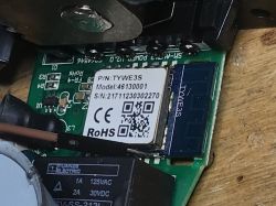
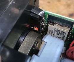
    @krzbor I didn't want to deconstruct it more for analysis but in this photo you can see one of the buttons testing the condition of the gearbox:
    Close-up of an electronic component with a visible control button and a board with a QR code. .
    @12robert12 very good tip!
    @ro-x important points you raised, have you perhaps measured how much power this type of valve needs? I haven't checked this myself yet, I need to look into it
    Helpful post? Buy me a coffee.
  • #7 20752562
    krzbor
    Level 27  
    p.kaczmarek2 wrote:
    @krzbor I didn't want to disassemble this more for analysis but in this photo you can see one of the buttons that tests the condition of the gearbox
    .
    So as I am guessing this is a "limit switch" based solution. How does the relay work? Does it work by interchanging the "+" and "-" fed to the motor? I understand that the limiters are not controlled by a microprocessor? I'm interested in controlling the motor itself, as I'm considering the possibility of using it for intermediate openings (not just open-close).
    However, if the system is based on the limiters, it's easy to burn out the motor when things get jammed.
  • #8 20752590
    ro-x
    Level 14  
    p.kaczmarek2 wrote:
    @ro-x important points you raised, have you perhaps measured how much power this type of valve needs? I haven't checked this myself yet, I need to look into it
    .
    Just for quick reference, a branded, PZH approved, NC type, 1" diameter solenoid valve, powered by 12V draws about 30-35W. The same valve with a solenoid on 230V consumes about 25-30W. It can be used for both water and gas. The cost is around £500.
    Assuming we want to do the subject properly, we buy two of these, add to it a buffer power supply with a 18Ah battery and our wallet will be depleted by circa 1500zł, and the monthly cost of use will be something around 45zł. Thick :) .
  • #9 20752837
    Anonymous
    Level 1  
  • #10 20752839
    ro-x
    Level 14  
    Jarzabek666 wrote:
    ro-x wrote:
    To be reliable, one needs a buffer power supply. The second, it needs wifi, so the whole network and server infrastructure also needs to be under a specific UPS. But what if there is a leak or a fire, when the power is out for a long time, and the UPS batteries give up? Well, that's a bummer. Such a solution is a bit of a stopgap
    .

    Valves like this have been around for a good couple of years, they are on supercapacitors so they don't need an external power supply to trip the closure, and the control is very simple it is open voltage, loss of voltage closes it.

    Can you give an example?
  • ADVERTISEMENT
  • #12 20753243
    ro-x
    Level 14  
    Thanks! This is exactly what I need :) I see that the valve draws only 6W. This is as acceptable a value as possible. In many installations you should be able to find a spare 0.5A directly in the alarm system, so we have power backup for free.

    Tell me more please, do you perform an on/off with it every so often so it doesn't stagnate? Does it run smoothly after extended periods of inactivity?
  • #13 20753278
    Anonymous
    Level 1  
  • #14 20753333
    ro-x
    Level 14  
    Have you measured its energy consumption when it is at rest, i.e. when it is fully charged and not moving? If it consumes less than 6W 99.9% of the time, it is a killer for me.

    The loudness of the valve, which is only supposed to operate in emergency situations, is a negligible issue. I'll probably be screaming louder then :) .

    And an open question. What is the end of life of a supercapacitor and how can this be measured, other than purely manual tests of valve operation every few months?
  • #15 20753376
    Anonymous
    Level 1  
  • #16 20753397
    ro-x
    Level 14  
    I'll buy one for trial + a couple of PP connectors and do a review. The plan - control from the Satel Integra via relay and powered from the APS-412 buffer power supply plus integration with Home Assistant via API in the ETHM module. It promises to be very cool :) .
  • #17 20754222
    krzbor
    Level 27  
    Let me repeat my question:
    krzbor wrote:
    That is, as I am guessing it is a "tie-rod" based solution. How does the relay work? Does it work by interchanging the "+" and "-" fed to the motor? I understand that the limiters are not controlled by a microprocessor? I'm interested in controlling the motor itself, as I'm considering the possibility of using it for intermediate openings (not just open-close).
    .
    Perhaps someone knows the answer?
  • ADVERTISEMENT
  • #18 20754255
    p.kaczmarek2
    Moderator Smart Home
    @jarzabek666 very good suggestion, as the 25W from @ro-x would be overkill for me, although maybe I look at it too harshly.... I, against all odds, have not replaced all the devices in the house with such "smart" ones, it's a shame to waste energy like that and introduce further complications to a system that has worked well for several decades, what I present on the forum is already flashing almost always for non-technical friends, sometimes for readers, etc.

    krzbor wrote:
    are controlled by the microprocessor?
    .
    I haven't removed the PCB any further so unfortunately I don't know if there's an MCU in there yet, but I do know that the WiFi module definitely controls one GPIO and there's no endcaps connected to each other. What happens next I have not analysed. The same thing is repeated in many similar products. Type "valve" in our list:
    https://openbekeniot.github.io/webapp/devicesList.html
    Helpful post? Buy me a coffee.
  • #19 20754932
    krzbor
    Level 27  
    p.kaczmarek2 wrote:
    I haven't removed the PCB further so unfortunately I don't know if there's an MCU still in there, but I do know that the WiFi module definitely controls one GPIO and there's no endcaps connected to each other.
    I understand that only one GPIO controls a relay, and that relay controls the servo circuit? Maybe I'll say why I'm asking this - I'm wondering if the circuit can be reworked to control any opening angle, not just on/off.
  • #20 20754998
    pier
    Level 24  
    I would like to see such a valve on my DHW pipe. The valve would shut off heating water when the temperature in the tank would be higher than the temperature on the boiler so that the boiler would not cool down the already heated water.
    I've been trying to do this for a while but I keep putting it off...
  • #21 20755136
    bsw
    Level 21  
    I was also looking for such a control so as not to replace the whole valve....
    As for the control:
    I don't think there's anything stopping you knocking the electronics out of the middle and using your own, which will work the way you want it to.
    The most important thing here is the mechanical solution - motor with gearbox with mounts and everything in a tasteful housing.
  • #22 20755140
    Anonymous
    Level 1  
  • #23 20757470
    krzbor
    Level 27  
    bsw wrote:
    I was also looking for such a control so as not to replace the whole valve....
    As for the control:
    I don't think there's anything stopping you from knocking the electronics out and using your own, which will work the way you want.
    The most important thing here is the mechanical solution - motor with gearbox with mountings and everything in a tasteful housing.

    It's a bit of a shame to get rid of the electronics - there's an EPS8266 in there and it's easy to program in an Arduino, for example. This processor can be used without WiFi or add Ethernet on SPI. I think I'm guessing how it's controlled - the relay has 2 pairs of contacts and probably depending on position gives "+" "-" or "-" "+" - i.e. it changes the direction of rotation of the motor. The limiters if NC allow current to flow both ways. In parallel to the limiters you just need to add diodes - then when it reaches the end it will stop, but in the other direction it will spin.
    To add control for any position you need to cut any motor power line and route it through an additional relay. Then you have directional control on the original relay and the additional relay allows you to interrupt rotation at any time.
  • #24 20757764
    bsw
    Level 21  
    krzbor wrote:
    It's a bit of a shame to get rid of the electronics - there's an EPS8266 in there and it's easy to program in an Arduino, for example.
    [..]
    To add control for any position you need to cut any motor power line and route it through an additional relay. Then you have directional control on the original relay and the additional relay allows you to interrupt rotation at any time.

    All nice if this ESP has free and available pins. I would need an RS485 bus to integrate it into my system :-) .
    In order to make a cool control to any position, a potentiometer - like in servos - would have to be added to the axis driving the valve....
  • #25 20758715
    krzbor
    Level 27  
    bsw wrote:
    All nice if this ESP has free and available pins. I would need an RS485 bus to integrate it into my system
    To make a nice control to any position you would have to add a potentiometer to the axis driving the valve - like in servos...
    .
    There are quite a few free pins - see photos - they are not even soldered. Adding a potentiometer is nice, but mechanically not that easy at all let alone trouble-free. If you don't expect frequent changes, the simplest method is to close the valve (i.e. wait until it is sure to close) and then time the opening. This should work out quite well and, incidentally, removes the problem of some inertia of the valve handle in relation to the actuator arm.
    The regulation can also be approached differently - if the valve is to regulate the flow of the heating medium, we can control the valve on the basis of the return temperature on a more/less basis - we do not need to know its position. Of course, a suitable algorithm is required.
  • #26 20768921
    jarekgol
    Level 39  
    You could try putting on an encoder wheel (like from an old mouse) not necessarily densely toothed and detect with a single photoelement without directional control. This should make the mechanics easier, you don't need to be as much on axis as with a potentiometer.
  • #27 20926699
    pier
    Level 24  
    If you don't want to get nervous, I recommend TASMOTIZER.
    A few clicks and the firmware is changed. I have never been able to upload anything via web service.

Topic summary

The discussion centers on the Jinvoo SM-AW713 WiFi-controlled valve overlay, specifically the ESP8266-based version branded also as SmartLED 8073, used for remote control of water or gas valves. The device requires external valves, which are not included in the kit. Users share experiences with integrating such valves into home automation systems, highlighting the importance of regular actuation to prevent valve stagnation and limescale buildup. The valve motor control is likely based on limit switches and relay-driven polarity reversal to change motor direction, with no direct microcontroller control of end positions. Suggestions include modifying the control circuit to allow intermediate valve positions by adding additional relays or sensors. Power consumption and reliability concerns are discussed, including the use of supercapacitors for power buffering, which enable valve closure without continuous external power. The typical power draw of solenoid valves and the cost of professional NC solenoid valves are compared. Integration with systems like Satel Integra and Home Assistant via relay and buffer power supplies is considered. Firmware flashing tools such as TASMOTIZER are recommended for ease of ESP8266 firmware updates. Mechanical robustness and potential for adding position feedback via potentiometers or optical encoders are also debated, with timing-based control proposed as a simpler alternative for flow regulation.
Summary generated by the language model.
ADVERTISEMENT