logo elektroda
logo elektroda
X
logo elektroda

Atmega Fusebit Doctor (HVPP + HVSP) - fix fusebits

manekinen 259606 342
ADVERTISEMENT
Treść została przetłumaczona polish » english Zobacz oryginalną wersję tematu
  • #61 8512511
    manekinen
    Level 29  
    Buddy, only in case we set the wrong clock. With reset or ISP off, only high voltage programming remains. I have already written about it in this topic ;)

    The last update was downloaded 56 times, it's a pity that no one adds new procks that have been brought back to life ... I'm also curious how the system works with procks in version V :)
  • ADVERTISEMENT
  • #62 8533456
    greg_001
    Level 12  
    Has anyone managed to bring the ATmega 128 back to life? I was programming with Burn-O-Mat and the program crashed. Next Avr no longer responds.
  • #63 8545715
    manekinen
    Level 29  
    Yes, one person wrote that she repaired the m128 - but the pins used by the doctor cannot be connected to other systems that may block communication - or serial resistors should be reduced to 100ohm.


    ADDED

    Good news, another user sent information that the system is doing great with Atmega2561 and Atmega128L

    gopelhu wrote:
    Hi Pawel again,

    Thank you very much again for your help.

    I tested your fusebit doctor and works perfectly with ATmega2561 and ATmega128L.
    Please check the attachment.

    Thanks again.

    Best Regards,
    George
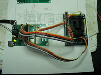
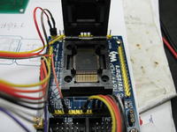
    Atmega Fusebit Doctor (HVPP + HVSP) - fix fusebits Atmega Fusebit Doctor (HVPP + HVSP) - fix fusebits Atmega Fusebit Doctor (HVPP + HVSP) - fix fusebits Atmega Fusebit Doctor (HVPP + HVSP) - fix fusebits


    The photos show a great way to repair these procks, a universal stand connected with wires to the adapter socket. It has to work. There may be problems with the repair of the prock in some system, but as I wrote, you can change serial resistors from 1K to 100ohm and it should be able to do it :)
  • #64 8607885
    ElectroTom
    Level 25  
    Beautiful work as always.
    Congratulations and Regards.
  • #65 8714262
    manekinen
    Level 29  
    UPDATE # 5, 11/07/2010

    Batch version 2.06:
    - Atmega324P signature recognition has been fixed
    - correct timing signal added for Attina15 on PB.3
    -fixed data bug in command "chip erase" for HVSP
    -added additional data for Attiny15 in command "chip erase"

    It would be nice if someone checked how the system behaves with Attina15.

    Rest unchanged, fuses as they were, i.e. internal 1MHz clock, EESAVE on (H: 0xE1 L: 0xD1)

    I would like to add that the system took third place in the summer DIY competition on the electrode and thus my workshop was enriched with new equipment - thanks for the votes!

    As always, have a nice release ;)
  • ADVERTISEMENT
  • #66 8882947
    Jacek M
    Level 13  
    Hello
    Maybe someone will find a description of my adventure with "Atmega fusebit doctor" useful (if he has similar problems).
    I found the project on the Internet: http://diy.elektroda.eu/atmega-fusebit-doctor-hvpp/
    I had a problem and I'm starting to doubt myself a bit. I assembled the system (I only have a depleted version for the Atmega 8 repair socket - DIL28, I skipped the rest), I programmed Atmege8 (batch version 2.6 - verified correctly, coffee grounds set, eprom clean), I checked all connections (no short circuits and interruptions, voltage ok) in relation to of the original, I only changed the BC557 to the BC558B (I had just one and the parameters do not differ much). Unfortunately, the system does not recognize the blocked Atmeg8 (3 pcs and additionally one, but this one is rather compacted) - the red LED is on, after RS I have the signatures: FF FF FF and on the beaten 00 01 02, after inserting a working Atmegi168 into the "doctor" (working - the programmer "sees" and programs it) I also have an unrecognized system and after RS: FF FF FF. In the next step, I uploaded the older version to Atmega 8 (2.3 + eprom and of course verified, the grounds were set) - unfortunately the same situation. In the next step I changed the resistors R7 to R23 to 150 ohms, but that didn't change anything either. Another thing I noticed was that when the repaired system is in the socket in the female goldpin connector on + 5V, when idle, I have about 4V (when there is no system, I had 0V - and I checked before) - that is, a problem with the transistor - I changed it to a good one (although the previous one was also good) on the BC560C, but it did not help, so I additionally pulled the mass to the collector through a 1k resistor - unfortunately nothing has changed. At this point, I ran out of ideas - I left the layout for 2 days. I started searching on the Internet and found on Elektroda https://www.elektroda.pl/rtvforum/topic1716521-30.html batch with the Atmega168 version (that's what I should start with), set the coffee grounds, uploaded the ROM and EPROM, mounted it on the plate and ... .. three Atmegi8s seasoned in a dozen or so seconds :) , the one I suspected that the slaughtered, unfortunately, could not be repaired (but I expected it). So the final conclusion - for those who have problems with the system - sometimes it is worth taking into account that something is wrong with the processor - although the programming is verified and it works efficiently in other applications (in my case, a vacuum gauge), I will only add that this system (not fully functional) has a broken P3 leg (I did not need it in the blood pressure monitor) and a PD4 repaired (but it works well).
    Maybe someone will find this description useful.
    And of course a big applause for the author of the project.
    best regards
    Jack
  • #67 8907002
    sykulec
    Level 11  
    Hello !! Could you send the PCB correct but in eagle ?? because those in the packages do not have GND ... and I do not know why when printing from PDF the size is smaller than the one from the eagle and the feet do not fit ... Regards.
  • #68 8907532
    manekinen
    Level 29  
    When printing from PDF, you should disable all scaling and adjustment of print sizes, the printing should be 1: 1. Well, unless it's a bug on my side, but no one has reported problems with my pdfs yet, they are generated with eagle and not by a virtual printer, so it should be ok.

    As for eagle printing, after loading the BRD file, click the RATSNEST button.

    Jacek M. - in the attachment program 2.06 compiled for atmega168 :)


    ADDED 27th Dec
    I also added compiled program 2.06 for atmegi88. Both tested.
  • #69 8908346
    Jacek M
    Level 13  
    Hello
    Thanks again for the new batch :) although now thanks to this project an additional 3 working Atmega8 have arrived :) (basically 2 - because one has already been used ;) ).
    When it comes to printing with Eagle - I do it a bit differently. When I have arranged everything (displayed items from the options Display ) exports as an image ( File - Export - Image monochrome - 600 dpi resolution) and then sometimes in the graphics editor, sometimes some minor corrections. The file obtained in this way prints directly on chalk paper without scaling (1: 1) and then - you know - thermo-transfer. Maybe someone will prefer this method.
    Jack
  • #70 8909998
    giovaniPL
    Level 11  
    I highly recommend this layout :) I was able to put mege8 and mege32.
    I see rs232 on the board, one pin goes to the atmegi8-doc (TxD) and the other to ground and I have a question here, how should I connect it to see information about the process, maybe it's a stupid question, but I'm a beginner in this. So, I have a programmer with the FT232RL chip and I read that I can convert it to a virtual COM TTL port, the MOSI pin transforms to Tx.
    I have to connect it only with myself ???
    And what program should I use for this? bascom emulator?
  • #71 8911269
    manekinen
    Level 29  
    Firstly the basics ;)

    You connect the masses, Tx (transmitting) from the board you connect to Rx (receiving) on the FT232. Any terminal, I recommend HyperTerminal. Default settings, only change the speed to 4800bps.
  • #72 8914565
    giovaniPL
    Level 11  
    Yes, google. :)
    Thanks a lot :)
  • #73 8917349
    sykulec
    Level 11  
    Welcome back !! I made the circuit, I programmed the processor according to the fuses shown on scr, no diode lit up on the composite board, after thoroughly checking everything I was so desperate that I removed a piece of the board, from the gold female pin to the atmega 8 socket, but the system still did not work, I put it back together on a universal board, I have achieved success! The red diode is on, however, after pressing the rst button, the red diode goes out, the diode (white one in my case) blinks and the red diode comes on again ... :( What's the most interesting, when I connect the computer's power supply, the red one goes out and that's it, it doesn't light up again or light up white ... what could be wrong? :( I'm just learning microprocessors and electronics, so please be understanding ...
  • ADVERTISEMENT
  • #74 8917995
    manekinen
    Level 29  
    The first time there were some serious errors on the board. The board has fine tracks, tiny pads, and small gaps between them, and it's rather hard for a beginner to do. Unfortunately, I couldn't design it otherwise.

    After pressing the start button, the green diode should blink, but only twice and very quickly. Then the state of the LEDs is established.

    Information about the power supply and what is happening on the + 5V and + 12V lines after pressing the button will also be helpful.

    I also paste a short FAQ that I wrote on the project website, i.e. in what order to look for which errors:

    FAQ - często zadawane pytania i odpowiedzi wrote:

    -If the green LED is on, you can be 100% sure that the fusebits have been reset. If the chip still does not respond to the normal ISP programmer, it means it has a damaged hardware SPI or it has some other damage.

    -The system does not work, no LEDs are lit - serious errors on the board, incorrectly programmed processor.

    -The inserted circuit is not recognized (red LED) - measure the voltage. During idle time, measure the voltage on the +12 RESET and +5 SUPPLY lines in the female goldpin connector - they should be 0V or close to 0V. After pressing the START button, these voltages will drop to values close to + 5V and + 12V for about a second. If not, make sure you use good transistors and solder them correctly.

    -The system is still not recognized - errors on the board. Most often these are invisible short circuits between the paths.

    - The chip is still not recognized - now the only thing you can do is check what the doctor sends via rs232 - only then can I help solve the problem - because I'm not a clairvoyant, right? Don't ask me how to connect it, you can find a lot of information about it.

    -Signature given by rs232 is 00 01 02, FF FF FF, or 00 00 00 - the repaired system is damaged or there are still errors on the board.

    -The signature given by rs232 is something like 1E 90 00 or 1E 1E 1E, i.e. the signature has some sense, some numbers match and some are slightly distorted - the system is operational, initializes, there are short circuits on the DATA, BS, XA lines on the PCB .
  • #75 8920848
    sykulec
    Level 11  
    so yes, on the 1 patient pin (reset) the voltage is 12v all the time, on the pin 7 there is a voltage of 5v for a moment and when I release the button it drops to 0
  • #76 8920865
    manekinen
    Level 29  
    The reset should be the same. Check the transistors.
  • #77 8947290
    sykulec
    Level 11  
    I fixed it, but the impulse lasts very short and is impossible to "hear" on a normal meter, on the oscilloscope (unfortunately not fully functional) I was able to see that there is a voltage change to around 12v, is that what it should be like? is not the impulse too short ?? and, of course, the red diode goes out for the time the start button is pressed ...
  • #78 8947807
    manekinen
    Level 29  
    I don't know if I understood correctly your previous post ... Normally, these tensions should be close to zero. The system starts working when the button is pressed and released, and all repairs take less than a second. So both of these voltages must go up for about a second after the button is released, and then return to values close to zero - the program ends at this point, you can safely remove the chip. The state of the system is shown by LEDs.
  • #79 8947894
    sykulec
    Level 11  
    so once again, after putting everything together on the universal board, programming the system in accordance with the grounds shown on scr, the red LED turns on, after pressing the Start button, the red LED turns off, the white LED turns on and the red LED turns on, Power supply to the 12v system, power supply to the doctor 5v, for the time the button is pressed, the voltage on 1 patient's leg is very short, about 12v (as I wrote earlier) and on the 7th leg normally "seen" on an ordinary 5v meter. When idle, these voltages are 12-40 mV.
  • #80 8953448
    sykulec
    Level 11  
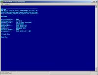
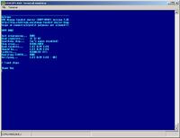
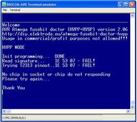
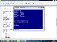
    I was able to do RS232 what the terminal showed: Atmega Fusebit Doctor (HVPP + HVSP) - fix fusebits I would like to add that the atmega 8 and atmega8-16 hit the table and it shows exactly the same. What hurts him? PS when no patient is inserted, the terminal shows only the inscription INIT PROGRAMMING.
  • #81 8954354
    manekinen
    Level 29  
    Short circuits on DATA lines. One bit is distorted, if you eliminate it, it will start nicely.
  • #82 8963294
    maximus22_kr
    Level 18  
    Hello
    Can you have the firmware for M16 and M32?

    best regards
    Peter
  • #83 8964666
    manekinen
    Level 29  
    Buddy, is m8 interchangeable with m16 or m32? Or maybe somewhere you saw a separate version of this system on such procks? So I have no idea why you ask about such ripples.
  • #84 8969542
    sykulec
    Level 11  
    I corrected a few solders, although there was no short circuit, there was a cold solder in 2 places :) A great project, a very useful thing, especially for those who are learning programming :) Best regards!
  • ADVERTISEMENT
  • #85 8992136
    darres1
    Level 13  
    Hello
    I made the layout and it works beautifully, but it didn't start right away, I made a few mistakes, but in the end I brought a few procks back to life.
    Pytanko to the author:
    In the beta version, the name of the processor is clearly visible

    Atmega Fusebit Doctor (HVPP + HVSP) - fix fusebits

    and not the next ones?
  • #86 9007740
    manekinen
    Level 29  
    You have everything in the subject and in the changelog in the package with the files. The program grew over time until the chip names finally ran out and they are not sent. The memory contains data for over 100 processors and a lot of code to handle both types of programming - hvsp and hvpp.

    By the way, one user discovered a bug in the program while trying to fix the AT90S8515 processor. As it turned out, a few older chips have slight differences in programming (other fusebit addresses, fusks and lockbits under one address, where normally only lockbits are) and there will be another update, but now I have no time for it. If someone has such older layouts, it will be great if he tries to read them in the doctor and tells you what the terminal is spitting out.
  • #87 9037565
    riger
    Level 24  
    Hello!
    I have the following problem. I put everything according to the diagram from the site: http://diy.elektroda.eu/atmega-fusebit-doctor-hvpp/
    Atmega programmed, no fuse bit because I don't need a counter. The situation looks like this:
    - no prock in the cradle (except ATMEGA8 DOC of course), no LED is lit, pressing the button does not do anything
    - ATMEGA8 as a repaired process - after connecting the power supply, the green LED will flash once and then the red LED will flash when the button is pressed, the situation repeats itself. This processor is definitely not released, but only has badly set fusebits.
    Any suggestions?
  • #88 9037599
    piotrva
    VIP Meritorious for electroda.pl
    manekinen wrote:

    gopelhu wrote:
    Hi Pawel again,

    Thank you very much again for your help.

    I tested your fusebit doctor and works perfectly with ATmega2561 and ATmega128L.
    Please check the attachment.

    Thanks again.

    Best Regards,
    George
    Atmega Fusebit Doctor (HVPP + HVSP) - fix fusebits Atmega Fusebit Doctor (HVPP + HVSP) - fix fusebits Atmega Fusebit Doctor (HVPP + HVSP) - fix fusebits Atmega Fusebit Doctor (HVPP + HVSP) - fix fusebits


    The photos show a great way to repair these procks, a universal stand connected with wires to the adapter socket. It has to work. There may be problems with the repair of the prock in some system, but as I wrote, you can change serial resistors from 1K to 100ohm and it should be able to do it :)

    how I would like to have such a tqfp stand ...
    could you ask the author where he got it and how much he gave for it ??
  • #89 9038828
    manekinen
    Level 29  
    riger - FAQ - https://www.elektroda.pl/rtvforum/topic1716521-60.html#8917995

    piotrva - I don't think you will get anything from the details ... http://www.waveshare.net/shop/M64+_ADP.htm - great stand, but with us it would probably cost a fortune.

    / added

    ATTENTION!
    In the last update (5), in the description in the appendix, I gave the wrong values of the grounds! It is H: 0xE1 L: 0xD1 a must be H: 0xD1 L: 0xE1 . If someone, using the ISP programmer, sent the exchanged fuses to the system, nothing bad happened, the system will not allow you to turn off SPIEN. The second focus is just "start-up time" so it doesn't matter here either, the system will work properly. I did not update the attachment because my previous post is too old to edit it, the updated attachment can be downloaded from the project's website.
  • #90 9039555
    riger
    Level 24  
    What RS232 spat out on me when I tried to unblock ATMEGI8:

    
    Welcome
    AVR Atmega fusebit doctor (HVPP+HVSP) version 2.06
    http://diy.elektroda.eu/atmega-fusebit-doctor-hvpp
    Usage in commercial/profit purposes not allowed!!!
    
    HVPP MODE
    
    Init programming...  DONE
    Read signature...    1E 93 07
    Searching chip...    (uc's names disabled)
    Chip erase...        DONE
    Read fusebits...     L:E7 H:D9 E:00
    Should be...         L:E1 H:D9 E:00
    Lockbits...          DISABLED (FF)
    Rewriting E1D900...  DONE
    Verifying...         L:E7 H:D9 E:00 - FAIL!
    
    Please try again...
    Usage in commercial/profit purposes not allowed!!!
    
    Thank You


    For the test, I also got MEGE16 but it was not blocked and the process ended successfully.

Topic summary

The discussion revolves around the Atmega Fusebit Doctor, a device designed to repair misconfigured fuse bits in AVR microcontrollers, particularly the Atmega series. Users share their experiences with the device, detailing issues such as incorrect fuse settings, inability to read signatures, and challenges in programming various Atmega models. Solutions include using the device to reset fuse bits, ensuring proper connections, and troubleshooting with UART communication. The conversation highlights the importance of correct voltage levels, resistor values, and the need for careful assembly to avoid short circuits. Users also discuss the potential for using the device with different AVR models and the necessity of firmware updates for compatibility.
Summary generated by the language model.
ADVERTISEMENT