logo elektroda
logo elektroda
X
logo elektroda

Atmega Fusebit Doctor (HVPP + HVSP) - fix fusebits

manekinen 260014 342
ADVERTISEMENT
Treść została przetłumaczona polish » english Zobacz oryginalną wersję tematu
  • #31 8302191
    manekinen
    Level 29  
    anelrob wrote:
    Hello.
    I made the layout according to your design and it works great.

    I only have a question whether the counter that counts the repaired microcontrollers gives any limitations or is it just such additional information.

    Atmega Fusebit Doctor (HVPP + HVSP) - fix fusebits

    I mean what restrictions? There are no limitations, it's just a counter, after each correct repair it increases by 1, when it reaches 65535 it will just start from zero. If I remember correctly, its value is stored in the last two eeprom memory cells.

    szymanczuk wrote:
    I quickly built a spider to test and unblock a few AVRs by the way, it helped me with ATMEGA644p ATMEGA16, ATMEGA8, and tiny2313, so a project worth recommending.


    Thanks, please report what has been repaired and what has not, I will complete the list and possibly some fixes in case of problems :)

    Duch__ wrote:
    Well, I would like a 168 atmega. I have nothing to do, and I can recover the blocked processors.

    The result code is attached, let me know if it works ...

    And on the page I actually had a typo, of course it should be 38,400, already corrected :)
  • ADVERTISEMENT
  • #32 8302445
    Kamlo
    Level 14  
    Hello

    I apologize to the author of the thread for fiddling with my codes (if it bothers me, I will edit it and create a separate thread), but I am writing about the current topic of microprocessor repair from a processor other than Atmega8.
    I have two AT8s locked and to unlock them I would have to buy 3 and build your chip which for me is rather unprofitable, congratulations on top fusedoctor project anyway.
    In connection with the above, I decided, in accordance with the atmega8 application, to unlock them with attina 2313 and this is how the code I provide at the bottom was created, the whole thing is connected on the contact plates (as can be seen in the attached photo HERE ), I did not draw the diagram because I think that the connection descriptions alone are enough. And they look like this:

    Attiny 2313 (doctor) Atmega8 (patient)

    Control signals
    PD0 BS1 (PD4)
    PD1 BS2 (PC2)
    PD2 XA0 (PD5)
    PD3 XA1 (PD6)
    PD4 XTAL1 (PB6)
    PD5 to LED through a resistor to GND
    PD6 WR (PD3)

    Data bus
    PB7 PC1
    PB6 PC0
    PB5 PB5
    PB4 PB4
    PB3 PB3
    PB2 PB2
    PB1 PB1
    PB0 PB0

    -Additionally, in Atmega8 (patient) OE (PD2) and PAGEL (PD7) back to GND
    - The RDY / BSY (PD1) port can be connected via a resistor to the led, it signals entering the programming mode, i.e. it is on almost all the time.
    -Power supply of both 5V systems and prepared 12V power supply needed to enter the programming mode
    -Power prepared so that only after turning on the doctor (attina) you can manually turn on the power to the patient 5V to VCC and AVCC and 12v to RST
    -Both systems without quartz

    Everything done according to the Atmega8 application (memory programming) and it should work and what ??
    DID NOT WORK either I made a mistake somewhere or my AT8s are locked to amen although they are in programming state. So I am asking if anyone would like to check what the problem is, I would be very grateful, the code, although a bit inelegant, is mostly described with comments so that you do not have to do too much research.

    In the appendix, apart from the code, there are already two compiled hexes, these are just two ways to enter the programming state (application s228):

    -AT8N_init1.hex method one:
    So after turning on the systems, when the diode (connected to the attina) is on, the patient reset (at8) should be connected to the gnd
    When the LED starts flashing, switch the reset to 12V
    Remembering that we have about 10 seconds for both operations (as part of the LED lighting / blinking)
    ? Between these activities, attiny must change the XTALL signal a few times, that's why it looks like this.

    AT8N_init2.hex second method:
    So first we turn on the doctor (attina) to 5V, which sets the appropriate states on the feet, when the diode (connected to the attina) starts flashing (practically immediately) we turn on the patient VCC and AVCC (at8) to 5V and RST to 12V.
    - do not scribble with this switching on, you should fit in (led blinking time)

    ps. with possible complaints about littering the thread, write do not be embarrassed, as I said, I will understand and start my own, this was just what I wanted to shoot into the current topic.

    best regards
  • ADVERTISEMENT
  • #33 8302517
    lucastg
    Level 14  
    If someone is going to start making the original tile, please send me info on private.
  • #34 8302762
    PO.
    Level 20  
    Fast: after write fuse for low byte you should reset xa1 and xa0 and replace them - unless a8 is otherwise ;) (I'm watching mine from a16), same fuse high.
  • #35 8302771
    raptor37
    Level 12  
    I have the EESAVE bit set at home, the data memory (flash) and EEPROM memory are loaded. However, the RS232 still crashes my bushes, just at the speed of 38400. And another question for the author of the project. What does the green LED on mean? Is it only reading the signature, or also checking the correctness of programming new fusebits?
  • #36 8303629
    Kamlo
    Level 14  
    PO. wrote:
    after write fuse for low byte you should reset xa1 and xa0 and replace them - unless a8 is otherwise

    Unfortunately, I checked it was not:
    
    C. Load Data Low byte
    1. Set XA1, XA0 to "01". This enables data loading.
    2. Set DATA = Data Low byte (0x00 - 0xFF).
    3. Give XTAL1 a positive pulse. This loads the data byte.
    

    Reset is with Load Address Low byte, but the address with fusses (probably?) We do not have to send, at least I have not seen anything like that in the application.
    Well, you will have to wait a few months for a new and (cheap) at8 series from atmel and build the main layout of this thread, out of curiosity whether it will unlock these cubes.
  • ADVERTISEMENT
  • #37 8303713
    PO.
    Level 20  
    Ah, because you see, in the datasheet from A16 there is a nice picture 131 where the waveforms do not match the description. I'm just biting on ;) .

    PS: Okay, these are my observations:
    you do not wait for rdy / bsy but you are driving after a delay with blinking - it should be longer but you do not know if something is happening or not ...
    if you give an impulse to wr or xtal, give a few nops, let the pin reload.

    I compare the datsheets from a8 and a168 and in one they have to wave 6x xtal and in the other wait 20us :) e.g. ... And they should program the same ...
    There is an additional fallback procedure:
    Quote:
    Note, if the RESET pin is disabled by programming the RSTDISBL Fuse, it may not be possible
    to follow the proposed algorithm above. The same may apply when External Crystal or External
    RC configuration is selected because it is not possible to apply qualified XTAL1 pulses. In such
    cases, the following algorithm should be followed:
    1. Set Prog_enable pins listed in Table 92 on page 227 to "0000".
    2. Apply 4.5 - 5.5V between VCC and GND simultaneously as 11.5 - 12.5V is applied to
    RESET.
    3. Wait 100 ns.
    4. Re-program the fuses to ensure that External Clock is selected as clock source
    (CKSEL3: 0 = 0'b0000) and RESET pin is activated (RSTDISBL unprogrammed). If Lock
    Bits are programmed, a chip erase command must be executed before changing the
    fuses.
    5. Exit Programming mode by power the device down or by bringing RESET pin to 0'b0.
    6. Entering Programming mode with the original algorithm, as described above

    In the usual procedure you don't need to do chip erase, you will do it to yourself with isp.

    I don't know how fast you have your hands with this reset and power connection :) , for a8 they make it "simultanously" and for 168 in the range 20-60us so congratulations ;) .
    I understand that you also exit programming mode by unplugging the plug.
    Plug in through the transistors and control both from the program, you'll know that it definitely does what it is supposed to do.


    Oh, there is no point in entering variables in hex, since you write the bits next to you anyway, give in binary, 0b instead of 0x.
    I do not count the coffee grounds, did you check that you set what you want? 0 programs, 1 clears the bit so you put the negative of what you want set.


    So much caught my eye, I try to find everything that may be wrong :P somehow these delays seem to me the most probable.
  • #38 8303874
    Duch__
    Level 31  
    manekinen wrote:
    Duch__ wrote:
    Well, I would like a 168 atmega. I have nothing to do, and I can recover the blocked processors.

    The result code is attached, let me know if it works ...


    Unfortunately it does not work. But I do not know if it is the fault of my chip which I converted to SMD (maybe I burned somewhere while soldering). So he made the circuit again, but with the through-hole method.

    Oh what I noticed. I program the chip via AVR-Burn-O-Mat. I was surprised that on Atmega8 your batch takes 8kb, and on atmega168 as much as 10kb, and there shouldn't be such a big difference when you change the device signature in the program. Have you changed anything else?

    What do you put on the prock batch? Can you make a screen with the fusebit settings by the way?
  • #39 8304029
    manekinen
    Level 29  
    Kamlo wrote:
    Everything done according to the Atmega8 application (memory programming) and it should work and what ??
    DID NOT WORK

    Connection error, I connected each line through a resistor for a reason. It is even written about it in the note that if the patient did not enter programming mode or other problems arose and the doctor did his job, we have a beautiful conflict of states on the lines and burnt ports.

    Likewise, the "prog enable" lines should be released right after the patient enters the programming mode, because here there may also be a conflict on the lines (I read in one of the notes) - you have PAGEL permanently to GND.

    The biggest BULL ... OE is the Output Enable line - that is, by pulling it down, the patient's data bus works as an output - with you all the time to GND so how come you want to send anything to the patient if his pins are the outputs? Check if you haven't burned those ports already :(

    Another thing, switching on a reset. Rather, it should be done according to what is given in the note, that is power, 100us, prog enable, 100ns, reset, 100ns. These are the minimum times, I was giving twice as much. For you, the reset is activated manually, I do not know how the processor will react to it. Perhaps the high state on RDY may be random, perhaps some code is being executed - and the processor has not entered programming mode at all.

    Additionally, as he wrote AFTER. In different notes, these programming mode firing sequences look slightly different. The times are different, the order is different, and in the older NIBY procks you have to wave the clock several times before starting anything - you do not need to ;) So I think I found 4 different ones, but I used only one because all the tested procks started up nicely. About this:

    
    1. Set Prog_enable pins listed in Table 27-12 on page 291 to “0000”, RESET pin to 0V and 
    VCC to 0V. 
    2. Apply 4.5 - 5.5V between VCC and GND.
    (Ensure that VCC reaches at least 1.8V within the next 20 µs.) - //nie koniecznie, nie mamy jak tego sprawdzić//
    3. Wait 20 - 60 µs, and apply 11.5 - 12.5V to RESET.
    4. Keep the Prog_enable pins unchanged for at least 10µs after the High-voltage has been 
    applied to ensure the Prog_enable Signature has been latched. 
    5. Wait at least 300 µs before giving any parallel programming commands. 
    

    I have increased these times a bit and it works very nicely. That's it for the hardware itself, I didn't look into the code because I don't sit in C, unfortunately. As for me, your post does not bother me here, I am glad that someone is looking at the notes and trying their own strength :)


    PO. wrote:
    In the usual procedure you don't need to do chip erase, you will do it to yourself with isp.

    Chip Erase is probably the simplest thing you can add at the very beginning. After that, we observe the state on the RDY pin and if it goes up, it means that the command has been carried out correctly and we already have the Action and Byte Select pins in order - and I had quite a problem with the same ones. I would like to add that without some display or UART, I can hardly see starting such a thing :(

    Duch__ wrote:
    Unfortunately it does not work.

    What symptoms?
    As for the batch size ... Code compiled under M8 takes 99% of its memory, and compiled (unchanged) on M168 takes 60% of its memory - bascom has a life of its own ;) In addition, in the code on the M168 you already have all the names of the procks after RS that were not included in the M8.

    I do not know where such problems with coffee grounds come from, after all, it is enough to set the internal generator and turn on EESAVE. The rest doesn't matter.
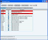
    I program via avrdude via bascom. I also use AVR-BURN-O-MAT, fuski:
    Atmega Fusebit Doctor (HVPP + HVSP) - fix fusebits

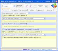
    I also use mkAVR Calculator, I recommend you to download and try the fusks:
    Atmega Fusebit Doctor (HVPP + HVSP) - fix fusebits
  • #40 8304181
    Kamlo
    Level 14  
    Quote:
    The biggest BULL ... OE is the Output Enable line

    Fortunately, only in the description, of course OE on 1.
    Quote:
    Likewise, the "prog enable" lines should be released right after the patient enters the programming mode, because here there may also be a conflict on the lines (I read in one of the notes) - you have PAGEL permanently to GND.

    Right, unfortunately I didn't have pins on the tiny attiny2313, I thought it wouldn't be such a problem.
    Quote:
    I do not know how fast you have your hands with this connection of the reset and power supply Smile, for a8 they have to do it "simultanously" and for 168 in the range of 20-60us so congratulations

    Quote:
    Another thing, switching on a reset. Rather, it should be done according to what is given in the note, that is power, 100us, prog enable, 100ns, reset, 100ns. These are the minimum times, I was giving twice as much. For you, the reset is activated manually, I do not know how the processor will react to it.

    As above, the power control requires additional pins (doctor), which I did not have, so I tried it manually, and as you can see, however, switching times are important in this operation.

    My suggestion was the layout of the manual programmer, http://www.ksw-funcard.civ.pl/FunCard/o_ukladzie.htm the author performs all the steps manually, apparently the new avr is not so easy to cheat.

    Conclusions: for success, there were a few ports in attiny2313 (this is the only one I had at hand) that I could control the power supply, reset, oe and pagel (patient), and ideally if there were even more to connect the lcd as the kol ~ manekinen suggested to have an insight into the whole process.

    Thank you friend ~ manekinen and PO. for being interested in the problem
    Best regards.
  • #41 8304286
    manekinen
    Level 29  
    Kamlo wrote:

    Fortunately, only in the description, of course OE on 1.

    Up yes, for the record itself. But when you want to read something from the patient, you have to direct the direction by pulling it down for the reading time.
    If there are any doubts, I will be happy to help, please ask.

    gufim wrote:
    Hello everyone, I have put together a Doctor and I have managed to unlock my Atmegs, so the system looks useful not only for those Atmegs that I managed to unblock today, but it will be very useful in the future

    Well, this is a guerrilla version, I advise you to give resistors for all lines - why? Read the post above. I am glad that it works, as you can see, it may be worth investing a dozen zlotys in an atmega8 to regain other blocked ones - the cost will pay off :) And if you like the layout, you can vote at the top of the page ;)
  • #42 8304407
    gufim
    Level 11  
    gufim wrote:
    Hello everyone, I have put together a Doctor and I have managed to unlock my Atmegs, so the system looks useful not only for those Atmegs that I managed to unblock today, but it will be very useful in the future

    Well, this is a guerrilla version, I advise you to give resistors for all lines - why? Read the post above. I am glad that it works, as you can see, it may be worth investing a dozen zlotys in an atmega8 to regain other blocked ones - the cost will pay off :) And if you like the layout, you can vote at the top of the page ;) [/ quote]

    Yes, maybe a guerrilla version, but it works as for the resistors, it may not be visible in this photo, but they are all according to the scheme and subsequent amendments, and as for voting, I have already voted and the fact is worth investing a few gold thinking in the future
  • #43 8304409
    anko6
    Level 10  
    I made a parallel programmer from http://elm-chan.org/works/avrx/report_e.html. I saved 2 m162 and one m8. I'm having trouble with the second m8. I receive information that it cannot read the signature and access to the Prock is not possible. Is this "doctor" to be able to fix a broken signature or the processor is trash. Probably the damage was caused by pulling the prock from the "spider" type system under the voltage of 5V.
  • #44 8304536
    manekinen
    Level 29  
    gufim - and there are actually resistors, I did not notice :)

    anko6 - the system heals tea leaves, but unfortunately it cannot do miracles. You can get rid of the other one because she is dead. The signature cannot be changed, it is not possible.
  • #45 8306015
    psine.pl

    RTV equipment specialist
    Hello.
    I made a copy of this device.
    Works great from the first start.
    I unlocked ATMEGE16 and ATMEGE32 (killed by my error in CODEVISION)
    Thanks.
    Big from me +
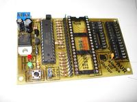
    In the attachment there is a photo of my PCB, I did not have the sockets at hand, I put together 2 of them :-)

    Best regards.
    Marek

    Atmega Fusebit Doctor (HVPP + HVSP) - fix fusebits


    Ah, I would have forgotten.
    programming (writing) procedure
    first I set ATMEGE8 to internal RC 8MHz + 0
    then I saved the hex file to the uC memory.
    then I saved the EEP file.
    finally I marked the EESAVE bit
  • #46 8306693
    manekinen
    Level 29  
    The most important thing is to NO do like this:
    1.eeprom
    2.flash
    3.eesave
    Because without the eesave bit, when loading flash, the content of the previously saved eeprom will be deleted. I did not mention it earlier because it seemed to be an obvious matter, but since this is a system for people who mistakenly blocked the processor by wrong fusebit setting, this information will probably be useful ;) The fusebit screens are a bit higher.
  • #47 8309280
    anko6
    Level 10  
    In the previous post I wrote that the parallel programmer each time I typed the "avrpp -r" command read a different signature value and further access to fusebit changes and programming was blocked. I was hoping that Atmega Fusebit Doctor would save my Prock, but unfortunately the Creator of this wonderful device dispelled my hopes. I was about to throw it into the bin, but it dawned on me that I would connect an external 200kHz generator to the test plate with Prock. I did and to my surprise it came to life. I set the correct fusebits and the slinger is OK !. For future reference, DO NOT PUT AND REMOVE THE PROCK UNDER VOLTAGE (5V). I did that often and it was good until then, but it is not known when some random impulse or impulse packet while pulling out of the stand will not damage something. In my case, the software could not read the signature because one of the damaged fusebits set to external RC. I hope Kol Manekinen will forgive me for writing off topic
  • #48 8309391
    manekinen
    Level 29  
    I wrote to you that she was dead, because I thought you tried to attach the generator or resonator - this is probably the simplest attempt to save a Prock, I wrote about it at the beginning ;) I believe in the automatic switching of the coffee grounds because it also happened to me, power surges and power outages during programming can work wonders, including changing the signature or irreversibly changing the coffee grounds :)
  • #49 8310724
    PF
    Level 19  
    Maybe you can try to help with my case.
    The circuit is folded up and works great [from the first kick it unlocked the M8] BUT:
    After connecting the power supply, the system works immediately, pressing the button as if it was turning it off and releasing it again. I have a momentary button that shortens when pressed - maybe it should be the opposite?!?. Further, after switching on without a "sick" system, the red diode lights up once. After disconnecting the power supply and turning it on again, there is a dead silence, none of the LEDs are lit until a chip is inserted.
  • #50 8314339
    piotrva
    VIP Meritorious for electroda.pl
    Thanks for the compilations for mega168, but such a question, are the outputs compatible with the original on mega8, have you changed anything else?
    if I find more time, I will put it on the contact plate.
    ps. it would be worth if you thought about such an isp-hvsp / hvpp adapter, because it would be a great project, because many people have an ISP and do not want to invest in the entire HV programmer, which gives more possibilities
    EDIT: as for the optimization, I would think about the second version controlled from the computer, then some operations, such as assigning a name to a signature, etc., could be dumped on the PC
  • #51 8314349
    PO.
    Level 20  
    You cannot switch SPIEN fusebit to ISP, so if you do, it's rather full HVPP ;) . Or why not full, all you need is a reblocker to properly secure your projects, already programmed by ISP :P .
  • #52 8315319
    piotrva
    VIP Meritorious for electroda.pl
    hmm, are you sure you can't ?? because it seems to me that it is only a security for your program, although I am not sure in this matter and I do not want to check :D
    and through SPI it is impossible to secure on lock-bits ?? isn't that what they were created for ??
  • #53 8315494
    PO.
    Level 20  
    piotrva wrote:
    hmm, are you sure you can't ?? because it seems to me that it is only a security for your program, although I am not sure in this matter and I do not want to check :D
    and through SPI it is impossible to secure on lock-bits ?? isn't that what they were created for ??


    Datasheet a16, p. 160, notes under table 105:

    Quote:
    Notes: 1. The SPIEN Fuse is not accessible in SPI Serial Programming mode.


    Of course, if we make a translator, it will be available from the Prock side, but I don't know what about the software, if it does not automatically allow access to this bit because it knows that we have no chance anyway.


    The question of what and how we secure is individual. There are companies that will physically burn your entire programming port so that you cannot unlock Prock by unauthorized methods ;) .
  • #54 8315766
    manekinen
    Level 29  
    PF wrote:
    After connecting the power supply, the system works immediately, pressing the button as if it was turning it off and releasing it again.

    The button is hooked up to a reset pin, which works just like that, and it's normal.
    PF wrote:
    Further, after switching on without a "sick" system, the red diode lights up once. After disconnecting the power supply and turning it on again, there is a dead silence, none of the LEDs are lit until a chip is inserted.

    After starting, the system waits for the high state on the RDY pin, when the processor is not plugged in, this high state is obtained by the internal pullup and the program continues to run. The fact that the red and green LEDs flash is normal because they share the pins with the XA0 and XA1 address lines. And why the system behaves this way without a patient inserted - I don't know - but that's probably the smallest problem ;) Perhaps the tension is building up too slowly and you need to set a longer delay in the coffee grounds. The system should be reset with the "start" button and not by cutting off the power.

    piotrva wrote:
    Thanks for the compilations for mega168, but such a question, are the outputs compatible with the original on mega8, have you changed anything else?

    No changes, only compilation, and as I mentioned, this program shows all names via uart.
    piotrva wrote:
    ps. it would be worth if you thought about such an isp-hvsp / hvpp adapter, because it would be a great project, because many people have an ISP and do not want to invest in the entire HV programmer, which gives more possibilities

    No problem, forum screenshot, I'm taking some time off, and there will be a deal ;) Buddy, I would like to, but I have no time at all :(
    piotrva wrote:
    as for optimization, I would think about the second version controlled from the computer, then some operations, such as assigning a name to a signature, etc., could be dumped on the PC

    Note a free uart pin - RX. It is such an open gateway that allows for the development of the project, it is possible to do so that the funds will be sent from the computer through the terminal :) The other side of the coin: the need to create usb-uart adapters etc, which increases the cost and complexity. Maybe someday...

    As for the possibility of changing SPIEN through the ISP - the manufacturer can write whatever he wants, I recommend trying it ;) Or how the producer explains that the signature may change, since it is impossible to do so in the notes. As for the support by programs, I don't think there will be a problem. In one of the avrdude overlays it is possible to change the signature and the avrdude itself supposedly allows it - it never worked for me - but the possibility is :) More here http://www.swiatelka.pl/viewtopic.php?p=35126#35126

    In addition, I have not tested the system with procks in the "V" version working from 1.8V.
    I gotrecently information that in the current state there are problems with these procks because the patient's voltage does not necessarily fall below this value at startup and there are problems.
    Humberto proposed such a solution - http://diy.elektroda.eu/atmega-fusebit-doctor-hvpp/comment-page-1/#comment-1052
    And apparently this fixes the problem, maybe someone can check it, please.
  • ADVERTISEMENT
  • #55 8315926
    piotrva
    VIP Meritorious for electroda.pl
    I am talking about changing the value of the SPIEN bit through SPI, because at a friend's lecturer at AGH, supposedly (I know it only from stories), students blocked SPI in several uP just using ISP for programming. The fault was apparently in the software they set the fusebits with, because it turned off SPI as the default option ...
    and I do not want to try myself, because then to unlock the procks, I would have to install the system from this project, or, having previously turned on JTAGEN, use such a programmer
  • #56 8350956
    manekinen
    Level 29  
    July 31, 2010 - UPDATE # 3

    Batch 2.04:
    -fixed some bugs
    -added support for new processors, 106 in total (138)
    - change of internal clock to 1MHz, UART baudrate is 2400bps

    ATTENTION, FUSEBITY! If you are upgrading a batch to 2.04, be sure to change the internal generator value to 1MHz. If you do the layout from scratch, the only thing you need to do is turn on the EESAVE bit - 1MHz is already set at the factory.

    Full list below:
    1kB :
    AT90s1200, Attiny11, Attiny12, Attiny13 / A, Attiny15
    2kB :
    Attiny2313 / A, Attiny24 / A, Attiny26, Attiny261 / A, Attiny28, AT90s2333, Attiny22, Attiny25, AT90s2313, AT90s2323, AT90s2343
    4kB :
    Atmega48, Atmega48P / A, Attiny461 / A, Attiny43U, Attiny4313, Attiny44 / A, Attiny48, AT90s4433, AT90s4414, AT90s4434, Attiny45
    8kB :
    Atmega8515, Atmega8535, Atmega8, Atmega88, Atmega88P / A, AT90pwm1, AT90pwm2, AT90pwm2B, AT90pwm3, AT90pwm3B, AT90pwm81, AT90usb82, Attiny861 / A, Attiny8585, AT90851585, AT90851585, Attiny88, Attiny
    16kB :
    Atmega16 / A, Atmega16U2, Atmega16U4, Atmega16M1, Atmega161, Atmega162, Atmega163, Atmega164, Atmega164P / A, Atmega165 / P / A / PA, Atmega168, Atmega168P / A, Atmega16, AT1690 / Attiny / A, Atmega16, AT1690 / P AT90usb162
    32kB :
    Atmega32 / A, Atmega32C1, Atmega323 / A, Atmega32U2, Atmega32U4, Atmega32U6, Atmega32M1, Atmega324, Atmega324P / A, Atmega325, Atmega3250, Atmega325P, Atmega32950P, Atmega32908P, Atmega32908P, Atmega32908P, Atmega32908P, Atmega32908P, Atmega32908P
    64kB :
    Atmega64 / A, Atmega64C1, Atmega64M1, Atmega649, Atmega6490, Atmega640, Atmega644, Atmega644P / A, Atmega645, Atmega6450, AT90usb646, AT90usb647, AT90can64
    128kB :
    Atmega103, Atmega128 / A, Atmega1280, Atmega1281, Atmega1284, Atmega1284P, AT90usb1286, AT90usb1287, AT90can128
    256kB :
    Atmega2560, Atmega2561

    Total 106 different CPUs supported.
    The slash along with P / A / PA means that the given processor in newer versions still has the same signature and fusebits, for example Atmega165 / P / A / PA includes Atmega165, Atmega165P, Atmega165PA processors. If you count it all separately, as it is in the lists of different programmers, 138 of them will be total.


    Please report bugs etc.


    Also, if anyone knows a processor that supports parallel or serial programming, powered up to 5V, please write.

    Here are the processors I have yet found that do not meet these conditions and at 99% NO will be supported:
    AT90scr100
    Atmega128rfa1
    Atmega16hva
    Atmega16hvb
    Atmega32hvb
    Atmega8hva
    Attiny4
    Attiny5
    Attiny9
    Attiny10
    Attiny20
    Attiny40

    :arrow: batch HEX, BIN, and Eeprom HEX, BIN, for the program version 2.04.
  • #57 8373580
    demsy
    Level 22  
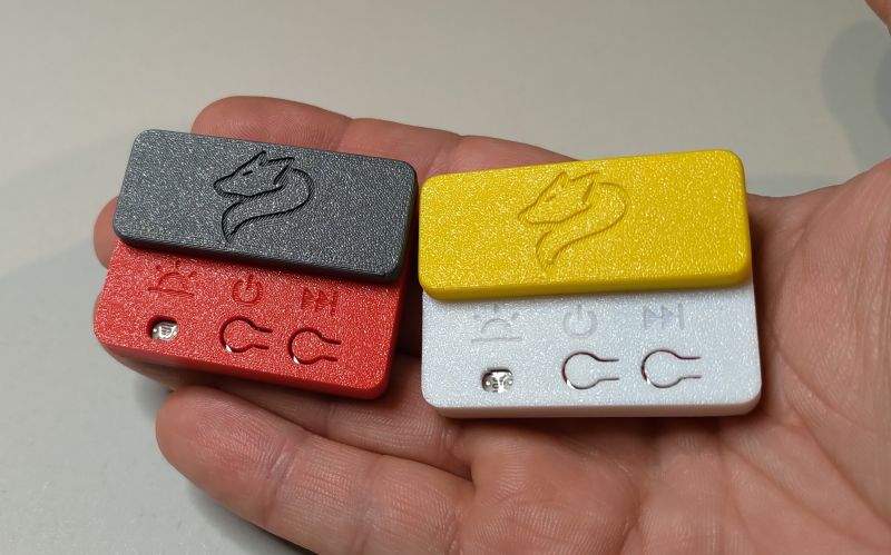
    Hello
    I have a question about tiles. What did a colleague mannequin with paint them from the side of the inscriptions with some colorless varnish?
  • #58 8375906
    manekinen
    Level 29  
    Hello, ordinary colorless spray enamel. You will find more on this topic HERE
  • #59 8410722
    manekinen
    Level 29  
    August 18, 2010 - UPDATE # 4

    Batch version 2.05:
    - no eeprom programming needed
    -improved support for 20-pin procks, including tiny26 repair bug fixed
    -improved recognition of the signature, when the first byte was 1E, the system considered it read correctly, however, there were procks that presented themselves as 1E 1E 1E. Now the second byte is additionally checked, it must be in the range h90 to h98
    -no names of prock after uart, after corrections the place has shrunk so that I decided to remove them completely - instead we do not have to upload eeprom :)
    - uart speed change again, now to 4800. Previous 2400 was just too slow and the program was repairing too slowly

    FUSEBITS FROM VERSION 2.04 NEED CHANGES, READ DESCRIPTION!

    (PS, in the previous update I forgot to change the version number and the layout was 2.03)

    Attached are HEX and BIN files of the batch 2.05

    I do not expect further updates, unless someone finds some bugs.

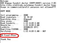
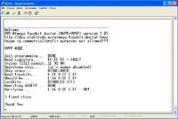
    And also a screenshot from the terminal ... tiny2313 procek which I just made for a friend, the fuses were nicely released because they were all FF ... I don't know how he did it ;)
    Atmega Fusebit Doctor (HVPP + HVSP) - fix fusebits

Topic summary

The discussion revolves around the Atmega Fusebit Doctor, a device designed to repair misconfigured fuse bits in AVR microcontrollers, particularly the Atmega series. Users share their experiences with the device, detailing issues such as incorrect fuse settings, inability to read signatures, and challenges in programming various Atmega models. Solutions include using the device to reset fuse bits, ensuring proper connections, and troubleshooting with UART communication. The conversation highlights the importance of correct voltage levels, resistor values, and the need for careful assembly to avoid short circuits. Users also discuss the potential for using the device with different AVR models and the necessity of firmware updates for compatibility.
Summary generated by the language model.
ADVERTISEMENT