logo elektroda
logo elektroda
X
logo elektroda

Atmega Fusebit Doctor (HVPP + HVSP) - fix fusebits

manekinen 259606 342
ADVERTISEMENT
Treść została przetłumaczona polish » english Zobacz oryginalną wersję tematu
  • #301 14160120
    manekinen
    Level 29  
    Because this avrdude has something kicked in its database, or does not get along with the programmer? I ran into the same problem with the 328P. It's about fuse extended. Extended byte reads 0x07 even though it is set to 0xFF, unused bits should always be written and read as ones, and avrdude reads them as zeros. So either send 0x07 there and you'll be ok, or ignore the error during verification.
  • ADVERTISEMENT
  • #302 14458406
    seba_x
    Level 31  
    manekinen, could you add the "Arduino Doctor" function for AtMega328, which would be to set the fuse bits and upload the bootloader?
  • ADVERTISEMENT
  • #303 14458866
    manekinen
    Level 29  
    Probably not, because if it is possible it requires a lot of work - you have to scribble all the functions for writing and reading flash memory. Added to this is the m168 or m328 procec to accommodate it all and additionally accommodate the bootloader batch itself.
  • #304 14527875
    Czang16
    Level 12  
    I have a fundamental question. How this Doctor works. :)
  • #305 14527892
    seba_x
    Level 31  
    HVPP = high voltage parallel programming = high voltage parallel programming.
    In the documentation of Atmel processors everything is explained.
  • ADVERTISEMENT
  • #306 14547318
    bolszoy26
    Level 12  
    Does anyone have the pcb pattern of the atmega 2313 smd adapter? On the Russian side, it does not work either ...
  • #307 14547351
    LA72
    Level 41  
    bolszoy26 wrote:
    And does anyone have the pcb pattern of the adapter atmega 2313 smd? On the Russian side, it does not work either ...


    ... maybe Attiny2313?
  • #308 14547401
    bolszoy26
    Level 12  
    damn you are right :)
    My mistake...
  • #309 14548824
    manekinen
    Level 29  
    Here http://mdiy.pl/atmega-fusebit-doctor-hvpp/
    In the download section there is a common SMD adapter for T2313, M8, M16, and M128. It seems that someone has already posted separate adapters on this topic. This Russian one was designed in some other program and it doesn't open in eagle.
  • #311 14616373
    drake68
    Level 13  
    Congratulations to the author of a great project, I recently mobilized myself to make this device, or actually I was mobilized by a pile of fallen AVRs.
    The results of the work of this system exceeded my expectations from the nine damaged ones
    processors came back to life after the therapy, seven pieces, two pieces were electrically damaged by applying too high voltage
    invaluable service for those who test AVRs in their systems.

    Atmega Fusebit Doctor (HVPP + HVSP) - fix fusebits
  • ADVERTISEMENT
  • #312 14625648
    RigelInOrion
    Level 13  
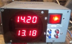
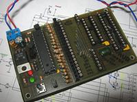
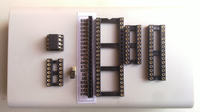
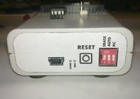
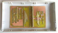
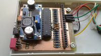
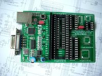
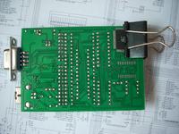
    Congratulations on the project as well. I modified the basic version a bit to get rid of the external power supply and pack the doctor in the housing. I saw converter diagrams for such projects somewhere, but the integrated circuits used there were hardly available. I did not work with the inverter based on M34063 (it worked once, sometimes it did not). So I used the ready converter module XL6009E1. I used ft232 for communication with the computer. Everything now works beautifully via the USB socket. A few photos of my sculpture. Best regards. Atmega Fusebit Doctor (HVPP + HVSP) - fix fusebits Atmega Fusebit Doctor (HVPP + HVSP) - fix fusebits Atmega Fusebit Doctor (HVPP + HVSP) - fix fusebits Atmega Fusebit Doctor (HVPP + HVSP) - fix fusebits
  • #313 14627510
    piotrva
    VIP Meritorious for electroda.pl
    As for the converter - you don't need that big.
    5V and so directly from USB, and 12 for programming can be done from a simple pump or a tiny integrated AM1P 0512SZ
  • #314 14628180
    RigelInOrion
    Level 13  
    I know it is a bit oversized for the doctor's needs, but since I got it as a gift, there was no point in looking for other uncertain solutions. At least it works stably. It's good to know about this integrated circuit for the future. Thanks @piotrva
  • #316 14737658
    aniołek
    Level 12  
    manekinen wrote:
    Here http://mdiy.pl/atmega-fusebit-doctor-hvpp/
    In the download section there is a common SMD adapter for T2313, M8, M16, and M128. It seems that someone has already posted separate adapters on this topic. This Russian one was designed in some other program and it doesn't open in eagle.

    "This Russian" adapter is made with Sprint Layout - something like electronic paint in relation to CAD. HERE home page where you can download either the demo version or the output file viewer only.
  • #317 14737686
    Gienek
    Level 37  
    A friend knows something, but not quite. DipTrace 2.4.0 and Sprint Layout are two different programs. You won't open this (pcb) file with Sprint Layout.
  • #318 14738006
    aniołek
    Level 12  
    Gienek wrote:
    A friend knows something, but not quite. DipTrace 2.4.0 and Sprint Layout are two different programs. You won't open this (pcb) file with Sprint Layout.

    Cheche - it looks like we are talking about different files, Sprint Layout opens .lay files (or at least the versions that I have been using for maybe 6 years :lol: :lol: :lol: ) ..
    But seriously - apparently we are talking about different tile patterns, hence the misunderstanding :wink:
  • #319 14738648
    Gienek
    Level 37  
    Actually, a misunderstanding. A friend wrote about post 309, and I wrote about 315.
    This Russian adapter is made in Sprint Layout, while the Fusebit Doctor modification is made in DipTrace 2.4.0.
  • #320 14857712
    Czang16
    Level 12  
    I have this question. How to lock the micro-controller for testing purposes to unlock it later thanks to the doctor? :) Thanks in advance for reply.
  • #321 14857721
    LA72
    Level 41  
    Czang16 wrote:
    I have this question. How to lock the micro-controller for testing purposes to unlock it later thanks to the doctor? :) Thanks in advance for reply.


    Disable SPI in fusebits. This is the most common problem.
  • #322 14857731
    Czang16
    Level 12  
    And after disabling this SPI I will be able to unblock it with "Doktor"? :)
  • #323 14857758
    LA72
    Level 41  
    Czang16 wrote:
    And after disabling this SPI I will be able to unblock it with "Doktor"? :)


    So far, the deal has not disappointed me.
  • #324 14858813
    dondu
    Moderator on vacation ...
    LA72 wrote:
    Czang16 wrote:
    I have this question. How to lock the micro-controller for testing purposes to unlock it later thanks to the doctor? :) Thanks in advance for reply.

    Disable SPI in fusebits. This is the most common problem.

    If the Czang16 coll. Uses USBasp or other serial programmer (MISO, MOSI, SCK + RESET) it cannot access SPIEN bit because:

    Quote:
    The SPIEN Fuse is not accessible in Serial Programming mode.

    so it may not be the most common problem.

    It can, however, change the function of the RESET pin to a regular pin, eg PC6 in ATmega8.
    It can also change the clock settings:
    - for e.g. external quartz and do not connect quartz,
    - or to an internal one other than the default setting eg 4MHz in ATmeag8 - this is the safest option and Fusebit Doctor will change back to the default 1MHz in this microcontroller.
  • #325 14859049
    manekinen
    Level 29  
    dondu wrote:
    If the Czang16 coll. Uses USBasp or other serial programmer (MISO, MOSI, SCK + RESET) it cannot access SPIEN bit because:

    Quote:
    The SPIEN Fuse is not accessible in Serial Programming mode.

    so it may not be the most common problem.

    Theoretically :) Just like the signature memory is absolutely inaccessible to write or erase, its theory and practice its own.
  • #326 14859103
    dondu
    Moderator on vacation ...
    manekinen wrote:
    Theoretically :) Just like the signature memory is absolutely inaccessible to write or erase, its theory and practice its own.

    No no. SPIEN differs from signature with an errata:

    Quote:
    3. Signature may be Erased in Serial Programming Mode
    If the signature bytes are read before a chiperase command is completed, the signature may
    be erased causing the device ID and calibration bytes to disappear. This is critical, especially,
    if the part is running on internal RC oscillator.
    Fix / Workaround problem:
    Ensure that the chiperase command has exceeded before applying the next command.

    Therefore, the signature may be damaged, but it is not possible to accidentally disable SPI during serial programming, because if it were so, it would be mentioned in errata.

    By the way, I had to recover the signature recently, which of course was done by a well-known and respected specialist doctor: Fusebit Doctor :please:
  • #327 14860450
    Czang16
    Level 12  
    Gentlemen, I have a problem with my doctor. If the doctor is turned on and the Atmega is put in its place, after pressing the button the diodes do not respond, but when I take the Atmege out, the green diode will flash 3 times quickly and the red diode will light up. Thank you for your answer and your time. :)
  • #328 14861212
    manekinen
    Level 29  
    dondu wrote:
    No no. SPIEN differs from signature with an errata:

    Well look somehow I have not seen her before, I think they had to add it later and my archive of notes is "deko" out of date :)

    Czang16 wrote:
    Gentlemen, I have a problem with my doctor. If the doctor is turned on and the Atmega is put in its place, after pressing the button the diodes do not respond, but when I take the Atmege out, the green diode will flash 3 times quickly and the red diode will light up. Thank you for your answer and your time.

    Check the doctor's operation on a working system. If there is a problem, look for errors on the board.
  • #329 14862733
    Czang16
    Level 12  
    I checked my doctor on a working system and it is still the same. :(
  • #330 14862831
    dondu
    Moderator on vacation ...
    There are no miracles, wrong assembly or wrong 12V power supply.

Topic summary

The discussion revolves around the Atmega Fusebit Doctor, a device designed to repair misconfigured fuse bits in AVR microcontrollers, particularly the Atmega series. Users share their experiences with the device, detailing issues such as incorrect fuse settings, inability to read signatures, and challenges in programming various Atmega models. Solutions include using the device to reset fuse bits, ensuring proper connections, and troubleshooting with UART communication. The conversation highlights the importance of correct voltage levels, resistor values, and the need for careful assembly to avoid short circuits. Users also discuss the potential for using the device with different AVR models and the necessity of firmware updates for compatibility.
Summary generated by the language model.
ADVERTISEMENT