logo elektroda
logo elektroda
X
logo elektroda

Atmega Fusebit Doctor (HVPP + HVSP) - fix fusebits

manekinen 259630 342
ADVERTISEMENT
Treść została przetłumaczona polish » english Zobacz oryginalną wersję tematu
  • #121 9288955
    piotrva
    VIP Meritorious for electroda.pl
    I may also test at home during the weekend, because for now there is less than 0 time to relax
  • ADVERTISEMENT
  • #122 9292457
    manekinen
    Level 29  
    Ok, I'm attaching update # 9 - March 13, 2011 :

    Atmega6490A / P, Atmega645A / PA, Atmega6450A / PA have been added
    Fixed not saving fuska extended in Atmega649A / P
    Fixed mass of chip names with A / P / PA suffix,
    this includes names in the terminal and names in the layout list

    A total of 145 supported chips.

    PCB: AVCC pin included, pullup for reset pin added - optional fix.


    The next version of the chip will use the RX pin, we will be able to send various things from the terminal :) I also propose to take this pin somewhere in a convenient place now :)
  • #123 9302675
    wiktor_m
    Level 12  
    Is there any simple way to unlock the debugWire (DWEN) bit in the Atmega168 (SMD) processor? Is this circuit suitable for this purpose? How many minimal connections do you need to solder to the processor to do this (I have soldered to the PCB, SMD)? I programmed this bit by accident using the ISP (in 4 processors, I set the bit and "went" to all of them) and now I have no connection with the system via ISP. Of course, I would not like to buy an expensive programmer (eg JTAGICE mkII) especially for this purpose. I do not need debugging myself, I just want to unlock to continue using the ISP.
  • #124 9303130
    manekinen
    Level 29  
    Of course, that's what this layout is for :)

    Unfortunately, you have to connect them all - there is no other option. If not, then unfortunately the replacement of circuits or the purchase of a programmer that will bite the debugwire.

    And the colleague hit it well, because yesterday the software version 2.10 was released - which allows you to save any coffee grounds, and not the factory ones as before. So you can change the DWEN bit itself without touching the others.


    Version 2.10 adds new functionality

    Soft 2.10:
    - you can talk to the doc via the terminal
    - you can choose systems with a damaged signature
    - any fusebits can be set
    - you can set any lockbits and delete them (by erasing the memory)

    If we connect the terminal's Tx pin to the doctor's Rx pin - the manual mode will start automatically. It is required that the Tx pin of the terminal is in the high state during idle time, it must pull up the 10K pull resistor. If it does not happen (incoming Rx connection disconnected), doctor will work in automatic mode (as before).

    WHAT AND HOW :
    First, doctor will read the signature. If the reading fails, it will ask you to type it in manually. Enter the last two bytes of the signature in HEX (4 characters) and hit enter.

    Then doctor will try to read the chip based on the given signature.
    If successful, choose one of the options:
    1 - write fusebits - write fusebits with values from the buffer (factory default).
    2 - modify fusebits - this option allows you to manually change fusebits, the data in the buffer will change. Enter one byte in HEX (2 characters) and hit enter. Repeat for each byte (if any).
    3 - set lockbits - enter the lockbyte value, one byte in HEX (2 characters) and press enter.
    Remember that unused bits must always be 1! For example, if you want to enable LB1 and LB2, enter FC (11111100)
    4 - erase the chip - erase all memory and lockbits, "allow erase" jumper is required for security.
    5 - end - finish programming and release the voltage - you can remove the chip.


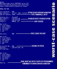
    This is how Attiny13 was repaired with a damaged signature:
    Atmega Fusebit Doctor (HVPP + HVSP) - fix fusebits

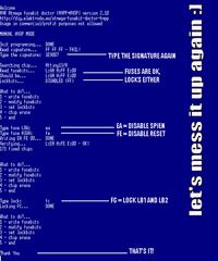
    And this is how the same circuit has been "broken" again:
    Atmega Fusebit Doctor (HVPP + HVSP) - fix fusebits

    Please do not be influenced by the LEDs in manual mode - they flash as they want :)

    Settings for the terminal as before, but let me remind you:
    baudrate: 4800
    parity: none
    databits: 8
    stopbits: 1
    handshake: none
    emulation: VT100


    The last two settings are important, without the former, we will not be able to send anything, and without the latter, we will see a few bushes at the beginning of the log - this is a terminal window cleaning sequence, works by default in Hyperterminal and Bray's Terminal, in others you may need to set it.

    PCB v.2h :
    - RX pin and 10K pull resistor added
    MUST add a resistor if you are upgrading to 2.10!
    Hope everything is understandable :) And one more good news for the end - the program is still in Atmega8 :)

    Attachment:

    NOTE the batch has a bug, in the post below corrected version 2.11
  • #125 9303423
    wiktor_m
    Level 12  
    Approximately how many connections would there be in the case of ATMega168? Does Fusebit Doctor use parallel programming? If so, it may take a while for a spider to connect.
  • #126 9304031
    manekinen
    Level 29  
    As I wrote, all of them. So 20. The charms of parallel programming ;)

    It may take a while to get connected, but it will certainly be easier than replacing the smd chips completely :)

    In the appendix and in the description, the colleague will find everything he needs, + note atmega168> memory programming> parallel programming.
  • #127 9309154
    kaeltaz
    Level 16  
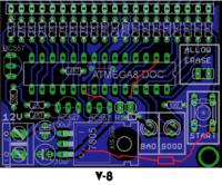
    I made a compilation of my colleague's version and I would like to ask if there are only 3 differences in pcb between version 8 and 10 because I made the chip in version 6 and I had to cleverly add 1 resistor and now I will have to make these 3 corrections. Adds a version comparison and the idea of making a fix.

    Atmega Fusebit Doctor (HVPP + HVSP) - fix fusebits Atmega Fusebit Doctor (HVPP + HVSP) - fix fusebits

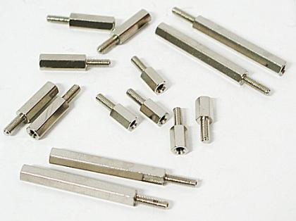
    Ps. There is no single hole on the plate at a distance and the plate is swinging.
    Atmega Fusebit Doctor (HVPP + HVSP) - fix fusebits
  • #128 9309210
    manekinen
    Level 29  
    After 1, not version 8 or 10 or 6 because you don't know what's going on. Plates are labeled sequentially 2c, 2d, 2e, 2f, 2g, and the last 2h :)

    Past 2:
    manekinen wrote:
    PCB v.2h:
    - RX pin and 10K pull resistor added
    MUST add a resistor if you are upgrading to 2.10!
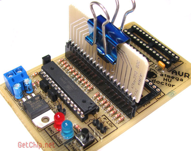
    My colleague forgot to add this resistor in his drawing, and it is important when updating the program to 2.10. Without it, the RX pin will be in a transient state and eggs will just happen. After that everything ok. Reset pull-up resistor optional, solder in case of problems.

    And one hole is missing. It can be made in the place of a power socket and the wires are soldered :)
  • ADVERTISEMENT
  • #129 9309317
    kaeltaz
    Level 16  
    It's about the differences between pcb 2e and 2h or there are only 3 differences between the versions marked in my post above (I marked the resistor in a circle in the second photo and it is gray in 1 photo).
  • #130 9312315
    manekinen
    Level 29  
    And there is actually a resistor, I did not notice :cry:

    There were no more changes, you can do :)

    2c - the first published version
    2d - resistor pulling the patient reset line has been added
    2e - a resistor pulling the patient's VCC line has been added
    2f - AVCC pin power supply added, this board appeared only in this topic
    2g - added pullup on reset pin
    2h - RX pin and pull resistor added.

    I have even more corrections glued on the board (from the bottom), because it was the first prototype board - 2a.

    // edit Mar 23
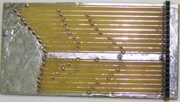
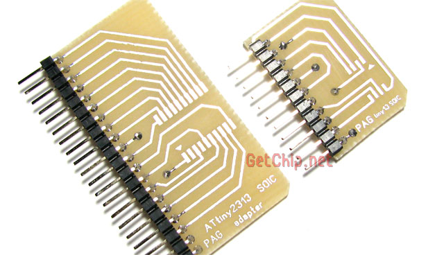
    If someone was interested in SMD adapters for circuits:
    Pin compatible with Attiny13
    Pin compatible with Attiny2313

    LINK
    about half way through the page
    If someone does not digest Cyrillic - LINK
    Although the description is the same as in the original.

    Atmega Fusebit Doctor (HVPP + HVSP) - fix fusebits
    Atmega Fusebit Doctor (HVPP + HVSP) - fix fusebits

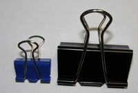
    Even a clothespin can be used, it only needs a strong spring.
  • #131 9481312
    tomeek1
    Level 9  
    I wanted to repair my atmega128 - unfortunately soldered to the board, most of the pins led out (not connected) except 3, PA0 - connected via 10k to 5V, XTAL1 and RESET as in the picture below. Will Doctor work?

    Atmega Fusebit Doctor (HVPP + HVSP) - fix fusebits
  • #132 9481347
    manekinen
    Level 29  
    The reset will have to be disconnected (raise the foot or cut the path) because this reset control system will interfere. A high current will flow through the internal protection diode.

    The resonator should not disturb.

    Added after 7 [minutes]:

    Oh, I completely forgot to post firmware 2.11 on the forum, fixed a terrible typo, fusek high did not save at all in version 2.10. Is it strange that no one noticed it here? :)
  • #133 9481413
    piotrva
    VIP Meritorious for electroda.pl
    well, the resonator disturbed me, as I once connected the ttl generator itself ...
  • #134 9514919
    fred114
    Level 12  
    I've been working on this contraption for a month now, I've already made two tiles and still have the following problems:
    1.When the power is turned on and the system is not put in for repair, two LEDs are constantly on.
    2. After putting in for repair, e.g. Atmega8, two LEDs will flash quickly when the power is turned on. After pressing the reset button, two LEDs will only flash.
    3. When I put the "repaired" Atmega into the programmer, everything is written by FF.
    4. After connecting to the terminal via com, such bushes appear and depending on which I set the transvers, there are different bushes.
    I have already checked the tracks several times FuseBits also set to L: 0xE1 H: 0xD1
    What else do I have to check
  • #135 9515681
    manekinen
    Level 29  
    Only the terminal can help.

    Please also provide the software version, board version, and in what mode you are trying to work (automatic or manual, it applies to software 2.10 and larger).

    If the terminal is spitting out bushes, and it is set up well, it could mean that the atmega-doctor's internal oscillator is not well calibrated and is far from 8MHz. In that case, you can try to connect an external 8MHz resonator and set it in the fusies.

    You can also paste a screenshot with terminal settings.

    fred114 wrote:
    3. When I put the "repaired" Atmega into the programmer, everything is written by FF.

    What is FF written?
  • ADVERTISEMENT
  • #136 9516029
    fred114
    Level 12  
    Thanks for the quick response. I use a batch and plate from atmega-hvpp-fusebit-doctor_update11.rar. I programmed several Atmrg8 with the same batch and the effect was identical. From the readme file I read that the setting of the grounds and quartz should be:
    FUSEBITS: internal 1MHz clock, EESAVE enabled:
    M8 L: 0xE1 H: 0xD1
    I set the clock to 1Mhz. Maybe that's the problem. I don't really understand
    what does "automatic or manual" mean
    I tried to paste the screenshot from the terminal with the transfer 34800 and 4800 (there are other bushes) but unfortunately I was not able to upload them to the site, I will try again.
    The firmware is version 2.11 and the board is also from this version. I have a question whether the 1kom resistors can also be a reason for bad display on the terminal? I read that you can use 330om. And by the way, I plugged the female plug directly to Coma. Maybe it is required. converter e.g. to max232 and hence there is such a problem.
  • ADVERTISEMENT
  • #137 9516109
    manekinen
    Level 29  
    fred114 wrote:
    I set the clock to 1Mhz. Maybe that's the problem

    My mistake! I rushed to 8MHz, it's supposed to be 1MHz of course ;)

    fred114 wrote:
    I don't really understand
    what does "automatic or manual" mean

    https://www.elektroda.pl/rtvforum/topic1716521-120.html#9303130

    fred114 wrote:
    I tried to paste a dump from the terminal at transfer 34800 and 4800

    I meant the terminal settings, not the bushes it picks up.

    fred114 wrote:
    I still have a question whether 1kom resistors can also be a reason for bad display on the terminal? I read that you can use 330om

    You can within such limits. I work with 1K.

    fred114 wrote:
    Maybe a converter is required, e.g. to max232 and hence the problem.

    Tragedy! Of course you need a converter, I thought that these are the basics you don't need to roll over and over again :(

    And by the way, correct the punctuation marks in the post, because for such mistakes, posts often go to the trash :(
  • #138 9516168
    fred114
    Level 12  
    Tomorrow I will make a converter for max232 and see if the ducklings are over. Unless there has to be a different type of converter. I read that they are version 3.3v and TTL. I think this option has to be TTL.
  • #139 9516328
    piotrva
    VIP Meritorious for electroda.pl
    Yes, it is supposed to be an ordinary converter to max232 (to TTL 5V standard). Unfortunately, but I dare to point out that by connecting the device directly to the COM port, the processor used as a doctor could be damaged (in RS232 there are -10V and + 10V states, and these processors from this family do not tolerate ...).
  • #140 9746613
    kaeltaz
    Level 16  
    I have a problem with the terminal, namely I am picking up the bushes. I made a manekinen design converter. What jumpers to short in the converter?
    Atmega Fusebit Doctor (HVPP + HVSP) - fix fusebits
    How to set up the terminal?
  • #141 9746685
    manekinen
    Level 29  
    I guess you built rs232 to attiny2313 converter

    It only supports speeds of 2400, 9600, and 38400. The Atmega Fusebit Doctor "broadcasts" at 4800 - so unfortunately none of that.
  • #142 9746698
    kaeltaz
    Level 16  
    It would not be possible to change the speed of the doctor?

    Ps. What speeds does the mirley's wheel converter support and is it possible to convert a colleague's converter.
  • #143 9746752
    manekinen
    Level 29  
    Do you have a problem with rescuing a prock? If you do not have another converter (I do not know if these can be modified to work at 4800), write what proc to compile the batch for - when I find the time I will send it. As an exception, because if I had to compile and publish dunks in 20 different versions for people with different needs, I would get tangled in it all ;)
  • #144 9746775
    kaeltaz
    Level 16  
    manekinen wrote:
    write to what procek to compile you batch
    Loading what? Converter? I noticed that my friend uses his converter in the video.

    Added after 50 [minutes]:

    Is it possible to change the transfer speed in the doctor to 2400 or 9600?

    Added after 4 [hours] 24 [minutes]:

    I will still ask if without a connected terminal, the voltage between tx and gnd in the doc should be 5v because with the converter disconnected from the USB, I still have power from the doctor.
  • #145 9748718
    manekinen
    Level 29  
    kaeltaz wrote:
    Loading what? Converter? I noticed that my friend uses his converter in the video.

    Yes, because the doctor used to transmit at 2400bps
    kaeltaz wrote:
    Is it possible to change the transfer speed in the doctor to 2400 or 9600?

    This is what I asked in the previous post. I can set it to 2400 but I ask what chip you have as a doctor.
    kaeltaz wrote:
    I will still ask if without a connected terminal, the voltage between tx and gnd in the doc should be 5v because with the converter disconnected from the USB, I still have power from the doctor.

    I think so, in the state when nothing is sent, there will be a high state, i.e. 5V. However, the RX doctora pin (where you have a resistor to ground) should be 0V when you have disconnected the converter.

    Added after 1 [minutes]:

    AHA, plates for atmega fusebit doctora will be available soon :) So if anyone else is planning to build, I suggest you wait :)
  • #146 9749278
    kaeltaz
    Level 16  
    Ok now I understand everything. :-) I have atmege8a-pu as a doctor. I will not use the tile because I already have a doctor in version 11, unless my friend is planning to release a new update with a new album? :-)
    PS. I'm waiting for the stick :-) . Thank you again.
  • #147 9749306
    manekinen
    Level 29  
    Ok in the attachment, version 2.11 with the setting 2400 - not tested.

    Tiles in the 2H version - nothing will be changed, no one reports any errors, so both the board and the soft are finally ok :)
  • #148 9749317
    kaeltaz
    Level 16  
    Does your colleague know how to set the jumpers in the converter in this case?

    Added after 2 [hours] 7 [minutes]:

    Unfortunately, I have the same x in the terminal. :-(
    Atmega Fusebit Doctor (HVPP + HVSP) - fix fusebits
    Now, after connecting the grommet and pressing the reset on the doctor, the diodes turn off. When sending something to the doctor, I also see x on the terminal. This is how the grommet works without any jumper connected.

    Added after 19 [minutes]:

    Do you set up a hyperterminal specifically?

    Added after 18 [minutes]:

    For each sign entered into the terminal with the patient attached, the doctor sends bushes. Maybe the grommet is bad.
  • #149 9773309
    mlassota
    Level 18  
    Hello colleagues

    Some time ago I was building uProg - a different layout from the Author of this project.
    Unfortunately, because of my indolence, I tried to program the Mega328P processor - powered by a 3V battery - with the USBAsp programmer operating at 5V.
    After the 2nd attempt (i.e. after the 2nd CPU :) ) I contacted a colleague mannequin to explain what I am doing wrong. It turned out that the catalog note describes the maximum voltage difference between the power supply of the target circuit and the programmer at the level of 0.5V. This was the cause of the death of these two processors.

    I asked a colleague mannequin o designing a set-top box / adapter to save processors in SMD casings - I wanted to check if, by some strange coincidence, the processors survived - they just blocked ...

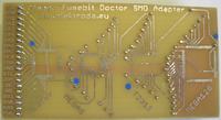
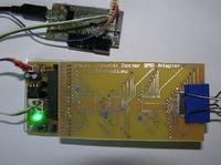
    Something like this arose:
    Atmega Fusebit Doctor (HVPP + HVSP) - fix fusebits Atmega Fusebit Doctor (HVPP + HVSP) - fix fusebits

    At this point, I would like to thank the author for designing both the Doctor and the adapter.

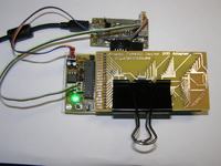
    I used such paper clips for mounting - they work perfectly
    Atmega Fusebit Doctor (HVPP + HVSP) - fix fusebits

    I cleaned the legs of the soldered circuits with a braid and attached to the adapter:
    Atmega Fusebit Doctor (HVPP + HVSP) - fix fusebits
    After a few tries - due to the lack of contact on the key feet - I got the following result:
    AUTOMATIC HVPP MODE 


    Init programming...  DONE 
                                                        
    Read signature...    7F 7F 7F - FAIL! 
                                            
    Trying T2313 pinout..7F 7F 7F - FAIL! 


    No chip in socket or chip does not responding 


    Please try again... 

    After pressing even harder, the log appeared:
    AUTOMATIC HVPP MODE 


    Init programming...  DONE 
                                                        
    Read signature...    1E 95 0F 
                                                    
    Searching chip...    no names in 8kB ver 
                                          
    Chip erase...        DONE 
                                                        
    Read fusebits...    L:46 H:D0 E:FD 
                                              
    Should be...        L:62 H:D9 E:FF 
                                              
    Lockbits...          DISABLED (FF) 
                                                
    Writing 62 D9 FF...  DONE 
                                                        
    Verifying...        L:62 H:D9 E:FF - OK! 
                                        
    35 fixed chips 


    Thank You 

    So the processor is operational ... I immediately started the second damaged processor and after the initial effect:
    AUTOMATIC HVPP MODE


    Init programming...  DONE
                                                         
    Read signature...    1E 97 1E 
                                                    
    Searching chip...    no names in 8kB ver


    Chip not supported.
     
    
    AUTOMATIC HVPP MODE


    Init programming...  DONE
                                                         
    Read signature...    00 07 07 - FAIL!
                                             
    Trying T2313 pinout..00 07 07 - FAIL!


    No chip in socket or chip does not responding


    Please try again...
    
    
    AUTOMATIC HVPP MODE

    I saw:
    AUTOMATIC HVPP MODE


    Init programming...  DONE
                                                         
    Read signature...    1E 95 0F 
                                                    
    Searching chip...    no names in 8kB ver
                                          
    Chip erase...        DONE
                                                         
    Read fusebits...     L:41 H:41 E:FA
                                               
    Should be...         L:62 H:D9 E:FF
                                               
    Lockbits...          DISABLED (FF)
                                                
    Writing 62 D9 FF...  DONE
                                                         
    Verifying...         L:62 H:D9 E:FF - OK!
                                         
    36 fixed chips
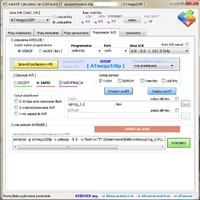
    They both live ... The remaining question of ISP efficiency. I connected to the programmer and read the signature - it started. To be sure, I uploaded almost 32kB soft and verified it - it was positive.
    Atmega Fusebit Doctor (HVPP + HVSP) - fix fusebits

    To check if the adapter is compatible with other processors, I tested it on:
    Mega8 Tiny2313 Mega32 Mega328 and Mega128
    The latter in the photos below:
    Atmega Fusebit Doctor (HVPP + HVSP) - fix fusebits
    Log:
    AUTOMATIC HVPP MODE


    Init programming...  DONE
                                                         
    Read signature...    1E 97 02 
                                                    
    Searching chip...    no names in 8kB ver
                                          
    Chip erase...        DONE
                                                         
    Read fusebits...     L:E1 H:99 E:FD
                                               
    Should be...         L:E1 H:99 E:FD
                                               
    Lockbits...          DISABLED (FF)
                                                
    Writing E1 99 FD...  DONE
                                                         
    Verifying...         L:E1 H:99 E:FD - OK!
                                         
    39 fixed chips


    Thank You


    So the adapter is suitable for saving even desoldered seemingly dead processors in SMD casings.
    I recommend it to everyone - you can significantly reduce the costs of our hobby :)
    Regards and thank you, my colleague mannequin for any help
  • #150 9774852
    manekinen
    Level 29  
    Thanks for this full description, it's nice that you tested the adapter with other procks - I didn't want to publish it, not knowing if there was any bug. And I couldn't do it myself because of problems with the printer :( But then I attach it in the attachment below, there are eagle light 5.10 project files and PDF versions.

    I would like to add that one of the electrode users who made the same mistake - he was programming the processor powered with 3.3V in 0-5V states - sent me three circuits to be checked in the doctory. The programming was done in such a way that it only saved flash without fusebits, write flash OK and then the system is dead - it does not respond to the ISP. So the suspicions are broken hardware ISP pins. When placed in a professional adapter ( Link and Link ) It turned out that two of them are alive and well! The Doctor fixed the fusebit setup and the setups fully functional. And fusebits?

    First: L: 81H :D 0 E: FF
    Second: L: 24 H: 8B E: FD

    So anything that cannot be set with the programmer. Setting CKSEL in general beyond the specification. One thing is for sure: in both cases the SAME fusebits shifted to some sort of random value - due to the programming voltage being too high.

Topic summary

The discussion revolves around the Atmega Fusebit Doctor, a device designed to repair misconfigured fuse bits in AVR microcontrollers, particularly the Atmega series. Users share their experiences with the device, detailing issues such as incorrect fuse settings, inability to read signatures, and challenges in programming various Atmega models. Solutions include using the device to reset fuse bits, ensuring proper connections, and troubleshooting with UART communication. The conversation highlights the importance of correct voltage levels, resistor values, and the need for careful assembly to avoid short circuits. Users also discuss the potential for using the device with different AVR models and the necessity of firmware updates for compatibility.
Summary generated by the language model.
ADVERTISEMENT