logo elektroda
logo elektroda
X
logo elektroda

Pinpointer vlf (mini metal detector)

Supermodurator 57430 18
ADVERTISEMENT
Treść została przetłumaczona polish » english Zobacz oryginalną wersję tematu
  • Pinpointer vlf (mini metal detector)
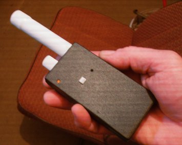
    It is an auxiliary miniature metal detector that is used for precision
    the location of small metal objects in the ground. With it, too
    we will determine the location of metal pipes in the wall or reinforcement bars in the ceiling,
    which is important when drilling holes there.

    Low-cost detectors and pinpointers as well as similar devices available for sale,
    whose descriptions and diagrams can be easily found on the Internet, work on a principle
    detuning of the LC circuit due to bringing the metal closer to L (coils - probes).
    The short range and strong susceptibility to the influence of the ground (earth) is their main disadvantage.

    The presented device works on a different principle. It has two coils of which
    one is the transmitter and the other is the receiver. Their mutual arrangement is such that
    that the influence of the transmitting coil on the receiving coil is minimal. Metal object,
    near them will upset this balance, causing them to grow
    amplitude and phase shift of the transmitter signal induced in the coil
    receiver (very simplified).
    This rule allows for much greater ranges as well
    minimizing the impact of soil mineralization on the detector operation.
    Unfortunately, it comes at a cost with the difficulty of making - especially the probe!
    The schematic diagram of the device (attached) is very simple.

    Basic features
    - operating mode - static
    - 10kHz frequency
    - ranges - 1 grosze over 5cm, 5gr- 6cm, for large objects over 20cm
    - does not react to stones containing iron compounds
    - low power consumption (9V - approx. 7mA)
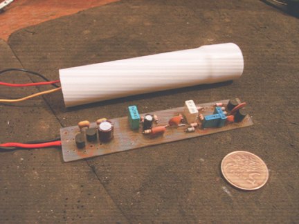
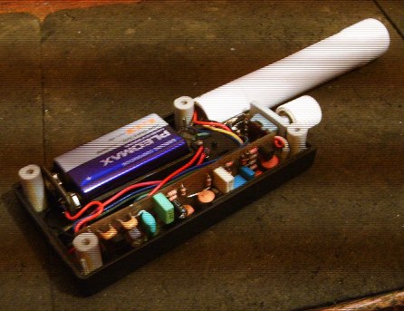
    - a tiny plate (8.5cm x 1.7cm)
    - sound signaling and LED diode (you can add vibrator)
    - the shape of the probe allows you to bury in the ground
    - low cost - made of readily available elements

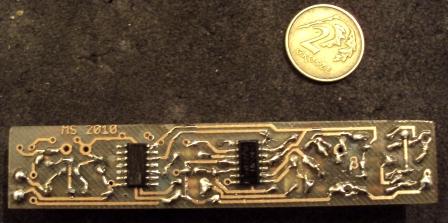
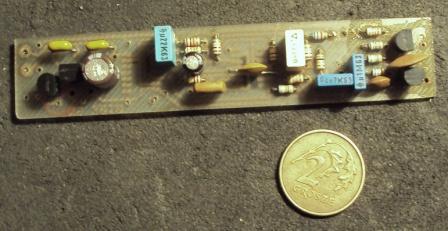
    Some details in the photos.
    Pinpointer vlf (mini metal detector) Pinpointer vlf (mini metal detector) Pinpointer vlf (mini metal detector) Pinpointer vlf (mini metal detector)

    Cool? Ranking DIY
    About Author
    Supermodurator
    Level 13  
    Offline 
    Supermodurator wrote 118 posts with rating 250, helped 2 times. Been with us since 2005 year.
  • ADVERTISEMENT
  • #2 8447418
    zgierzman
    Level 31  
    I like the project, I would do such a miracle myself. What frequency does it work at?

    I was very disappointed with the attachment. You only gave a schematic there that looks like a stripped down ALL1 detector, and there is no description of the probe structure. So for something that does not really bring anything new, you take a point commission in the section where it is not welcome ... But since I have already downloaded this diagram, I would be grateful for the description of the probe, for example on PRIV.

    Since you gave the amplifiers in the smd version, why are the rest of the elements threaded through? I understand that some capacitors must be like that, but the stabilizer, transistors, resistors are not ... And the board could be even smaller ;-)

    Regards
    Zgierzman

    EDIT:
    aha, I found it
    http://www.exploracja.cyberdusk.pl/phpbb2/vie...?t=12519&sid=b4bffed0fe709d4e26f186fc3de9d8f4 " target="_blank" rel="nofollow noopener ugc" class="postlink inline" title="" > http://www.exploracja.cyberdusk.pl/phpbb2/vie...?t=12519&sid=b4bffed0fe709d4e26f186fc3de9d8f4
  • #3 8447434
    Frog_Qmak
    Level 25  
    could you give a picture of the probe? Or explain its construction?
    nice design, + for originality, because it's kind of simple, and hardly anyone does it :)
  • #4 8447681
    Duch__
    Level 31  
    Hello.

    The device is made aesthetically. Could a colleague demonstrate a movie with action? Please put the data about the probe, because in the link provided by

    zgierzman wrote:


    I see that you presented the construction of the probe there, but personally I am not going to create another account to download one file.

    Regards. Spirit__
  • ADVERTISEMENT
  • #6 8448057
    Supermodurator
    Level 13  
    The probe is the most difficult to do. Necessary for its construction (regulation)
    there is a frequency counter and an oscilloscope.
    During construction, most of the rules we use apply
    by performing a "normal" VLF probe.
    The drawing will dispel any doubts. We wind all the coils
    in the same direction, marking the beginnings (or ends) - in the figure
    dots. During the winding of L1 and L3, we impregnate every 200 turns
    cyanopane. We connect according to the drawing, attach a capacitor to Tx
    100n. We attach the probe to the system, connect the power supply and measure
    frequency. If its value is near 10kHz then we try
    pre-compensate - by moving L2 over L3 we reduce the mileage
    (observing the oscilloscope screen) on Pin1 LM324 to as little as possible
    level. At this stage, the mileage can be kept to a minimum
    distorted (significantly differ in shape from the sinusoid).
    Now we select the Rx capacitor. For this, we temporarily connect
    winding the receiving coil in place of the transmitting coil. We are trying
    get resonance at a frequency slightly higher (approx. 200Hz) than Tx.
    After that, we correct the compensation and immobilize L2
    and cyanopanem tubing.
    After inserting the winding into the housing, pour resin.
    The face of the probe (the end we are looking for) in my case is L1 (Tx),
    although it seems indifferent.
    Then select the elements marked with an asterisk in the diagram
    in the phase shifter so that the detector reacts to all metals,
    a did not detect ferrite and stones containing iron compounds, and the course
    at its exit it was rectangular.
    At this stage, it may be necessary to correct the Rx capacitor,
    therefore it is a good idea to wait until this point with the probe housing.
    The coils do not contain any core, the fiber rod shown in the photos
    glass supports the mechanical construction.
    Point L1 in the assembly drawing is the common ground connection point
    all coils.
    Pinpointer vlf (mini metal detector) Pinpointer vlf (mini metal detector) Pinpointer vlf (mini metal detector) Pinpointer vlf (mini metal detector) Pinpointer vlf (mini metal detector)
    Pinpointer vlf (mini metal detector) Pinpointer vlf (mini metal detector) Pinpointer vlf (mini metal detector)
    A colleague from Zgierz wrote:
    Quote:
    You only gave a schematic there that looks like a stripped down ALL1 detector,

    Take a close look, what does it have to do with all1? Probably just the same
    solved phase detector - it is the same in many other detectors!
    Everything else is completely different ..
  • #7 8449748
    zgierzman
    Level 31  
    Quote:
    A colleague from Zgierz wrote:
    Quote:
    You only gave a schematic there that looks like a stripped down ALL1 detector,

    Take a close look, what does it have to do with all1? Probably just the same
    solved phase detector - it is the same in many other detectors!
    Everything else is completely different ..

    I dug up the ALL1 diagram, took a look and the fact - it seemed to me. I return my honor and sprinkle ashes on my head. My only excuse is that I probably made Alla three years ago, or earlier, and since then I have not returned to the pattern.

    Regards
    Zgierzman
  • #8 8452923
    2lero
    Level 12  
    As far as I understood the scheme correctly, the system examines the amplitude and phase with Rx. As for the amplitude, the matter is obvious to me, but why is the phase also tested?
  • ADVERTISEMENT
  • #9 8452973
    Supermodurator
    Level 13  
    Because thanks to this, the detector can distinguish colored metal from iron, you can also
    eliminate the influence of the soil.
    Anyway, you'd better read somewhere about system solutions and types of detectors.
  • ADVERTISEMENT
  • #10 8475331
    BOOF
    Level 11  
    Someone asked for versions in SMD. Here is the finished project. I post with the consent of the creator of this device.


    Pinpointer vlf (mini metal detector)
  • #11 8475535
    FoxTech
    Level 20  
    BOOF wrote:
    Someone asked for versions in SMD. Here is the finished project. I post with the consent of the creator of this device.

    Pinpointer vlf (mini metal detector)

    How can I etch the plate on the basis of such a picture?
    After all, this is an overview drawing and not a PCB design.
  • #12 8475639
    BOOF
    Level 11  
    I'm sorry, but I did not write that it is etchable. This is made in SprintLayout 5.0. This is the free version of this program and has some limitations. This includes on the fact that I can print a black and white version on a printer and make a pattern for e.g. thermal transfer, but I can only export in the form I did. I have given this for convenience only to potential contractors. Again, I'm so sorry.
  • #13 8475765
    FoxTech
    Level 20  
    BOOF wrote:
    This is made in SprintLayout 5.0. This is the free version of this program and has some limitations. This includes on the fact that I can print a black and white version on a printer and make a pattern for e.g. thermal transfer, but I can only export in the form I did.


    If you can print to paper, you can also print to PDF, it's very simple: use a free program called Bullzip PDF Printer. The description of the program explains all the confusions:

    Quote:
    Bullzip PDF Printer is a free application that allows you to save documents as PDF files in any program with the option of printing the page.


    Download from:
    http://www.dobreprogramy.pl/Bullzip-PDF-Printer,Program,Windows,12736.html
  • #14 8509547
    mopo11
    Level 2  
    I would like to ask for a list of all detector elements with exact parameters.
  • #15 8510953
    Supermodurator
    Level 13  
    Unfortunately, such a list has never been established - the layout has few elements, easy
    write them down from the schematic diagram.
    Miniature elements, 5mm raster.
    Both integrated circuits are SMD versions (SO14 housing).
    Electrolytic capacitors for a voltage of 6.3V.
    C5, C6 - ceramic.
    kisses
  • #16 8516659
    mopo11
    Level 2  
    I am asking for a list of these elements. so far I have been building only kits and I would like to make a pinpointer from scratch. I wrote down the basic elements from the drawing, but I cannot read some of them.
  • #17 8517652
    Supermodurator
    Level 13  
    There are some who have already performed this detector and such problems
    did not report ..
    Write specifically which markings raise your doubts?
    I adhere to it once again, as long as the device diagram is trivial
    simple, it's not like that anymore and it requires some experience!
    kisses
  • #18 8572544
    MnIrek
    Level 10  
    is it possible to insert a full PCB design in PDF

Topic summary

The discussion revolves around a miniature metal detector, specifically a pinpointer that utilizes a unique principle involving two coils—one as a transmitter and the other as a receiver—to locate small metal objects with precision. Users express interest in the device's construction, particularly the probe design and its components. Several participants request additional details, such as frequency specifications, a complete list of elements, and PCB designs. The conversation highlights the challenges in building the probe, including the need for specific tools like a frequency counter and oscilloscope. The importance of phase testing for distinguishing between different types of metals is also noted. Overall, the community seeks to share knowledge and resources to aid in the construction of this device.
Summary generated by the language model.
ADVERTISEMENT