logo elektroda
logo elektroda
X
logo elektroda

WARNING! Cheap step up / down converter - surprise ... XL6009

SylwekK 27501 56
ADVERTISEMENT
Treść została przetłumaczona polish » english Zobacz oryginalną wersję tematu
  • #31 17337823
    SylwekK
    Level 32  
    Unfortunately, your examples are completely wrong ;-)
    Szyszkownik Kilkujadek wrote:

    But here you are, first person:
    When installing LPG to a car, always have gasoline in the fuel tank. Even if you only drive on gas and the car does not start with LPG immediately. In the absence of gasoline, the fuel pump will seize up.

    The user is notified about it after the installation (the mechanic informed me). Besides, there are already two elements -
    fuel tank and a second LPG. It has nothing to do with the power situation in question.

    Szyszkownik Kilkujadek wrote:
    Another example? The aircraft manufacturer does not guarantee the correct operation of the engines if there is less than the recommended amount of fuel in the tanks.

    The answer contained in the quote "does not guarantee", but it does not mean that it will not make an emergency flight to the airport using the fumes.
    Szyszkownik Kilkujadek wrote:
    And what will happen if you fill with fuel with a lower octane number than the minimum recommended by the engine manufacturer? Well, it may not work properly.

    How many gas stations do you have where you make this mistake? :)
    Szyszkownik Kilkujadek wrote:
    Next? If it wasn't, an example from the electrical industry: What will happen if you supply the motor with a voltage below the rated voltage and load it with the rated torque? It will be warm. :-)

    And the most misguided argument ;-) Logic itself tells you that something is wrong here ... You give too little voltage and you are surprised that it does not spin - you have at least time to react before it turns bad - you make a mistake at your own request. In the case of the converter in question, the logic goes raspberry when it comes to the end result.
  • ADVERTISEMENT
  • #32 17337861
    Szyszkownik Kilkujadek
    Level 37  
    SylwekK wrote:
    The user is notified about it after the installation (the mechanic informed me).

    And the inverter manufacturer did not inform you about the supply voltage range?
    SylwekK wrote:
    The answer contained in the quote "does not guarantee", but it does not mean that it will not make an emergency flight to the airport using the fumes.

    Maybe it will, maybe it will not. But will you agree that the risk here is not taken by the producer?
    SylwekK wrote:
    How many gas stations do you have where you make this mistake?

    About 6,500 nationwide. There are known cases where small planes were refueled with car fuel rather than aviation fuel.
    SylwekK wrote:
    And the most misguided argument Logic tells us that something is wrong here ... You give too little voltage and you are surprised that it does not spin - you have at least time to react before you go wrong - you make a mistake at your own request. In the case of the converter in question, the logic goes raspberry when it comes to the end result.
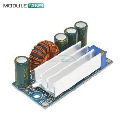
    You also have time to react when you supply the inverter with too low voltage and you see that the output is incorrectly voltage. Tell me on whose request the inverter got too low voltage? Who made the mistake? Producer or you?

    Perhaps my logic is different from yours. My logic: device powered by a voltage below the rated voltage = may not work properly. Provide the device with the correct power supply or disconnect it.

    What do you think are undervoltage protections in power engineering?
  • #33 17337983
    SylwekK
    Level 32  
    Buddy do you really see the subtle difference between this inverter and the examples you cite. Following this line of reasoning, you can assign here any item used contrary to the instructions, but we are talking about a low-voltage, battery device, I would even say, where completely contrary to logic and common sense, when the battery is gradually discharged, the voltage appears at the output immediately killing all electronics connected to the output which is not talked about (!). For me, this is clearly a design flaw. In all of your examples either there was information about the consequences, or you could easily draw logical conclusions as to what could happen if you consciously go beyond the scope. Find me an example appropriate to this converter or let's finish the discussion, because I personally do not know a similar case of such disinformation, and I gave this 1% of similar cases only because I am not alpha and omega and there are probably devices somewhere behaving inconsistently with logic and prediction I haven't come across yet.
    Read my post on this topic for the first time and make your own conclusions. best regards :)
  • #34 17338026
    Szyszkownik Kilkujadek
    Level 37  
    SylwekK wrote:
    contrary to logic and common sense, when this battery is gradually discharged, the voltage appears at the output, killing all the electronics connected to the output, which is not mentioned (!).

    You are not testing the behavior of the device operating outside the rated range? Before its final application, don't you do that? You definitely do.
    The aircraft manufacturer also does not say what will happen when you fill up car fuel instead of aviation fuel. It says what needs to be flooded and that's it. Will you pour less octane? Well, it is logical that if your life is nice then not.
    SylwekK wrote:
    In all of your examples either there was information about the consequences, or you could easily draw logical conclusions as to what could happen if you consciously go beyond the scope.

    I agree that the inverter behavior described by you may be surprising. I agree with that from the beginning. But I repeat: no one should be surprised that some device (especially a cheap mass market from China) plays tricks when working in non-rated conditions.
    Thanks again for the warning. It stuck in my memory. I did not know this effect of converters. Although when I analyze now, I think I understand where it comes from.
    So much for me.
  • #35 17338034
    Slawek K.
    Level 35  
    Colleague @sylvekk He is right, because everyone in this case would expect that when we give the input a voltage lower than the recommended one, the converter will not spit anything out at the output or it will give a voltage lower than the set voltage, and here is a completely different result, definitely unexpected.

    Greetings
  • #36 17338096
    Szyszkownik Kilkujadek
    Level 37  
    rs6000 wrote:
    everyone in this case would expect
    Not everyone.
  • ADVERTISEMENT
  • #37 17338113
    Slawek K.
    Level 35  
    As I can see from the discussion, you really don't, I respect it.

    Greetings
  • ADVERTISEMENT
  • #38 17338175
    Szyszkownik Kilkujadek
    Level 37  
    I'm no longer. Thanks mate @sylvekk
  • #39 17766689
    wosiekpl
    Level 21  
    Hello

    The topic of this test is very interesting. Since I bought two such power supplies, I have a question about this.
    Well, I want to use one of them to power the Arduino Uno. The input voltage will be taken from the 24 Vdc 4.2 A switching power supply, then it will be reduced to 12 V and this will be the power supply for the Arduino board. And the question that arises is whether I should not use a protection on the output of this module?
    I am asking because, reading what is described in this topic, I am afraid that when the voltage drops after switching off the switching power supply, at these 3.4 V the output voltage may appear higher than 12 V and damage the Arduino.
    (or maybe such a case will not occur here because in the switching power supply there is no large capacitor at the input and what I am writing does not make sense here?)
  • #40 17766732
    Slawek K.
    Level 35  
    Why heat a linear stabilizer on arduino by supplying 12V from the inverter, the minimum supply voltage is 7V and it is proposed to set it on the inverter.

    Kisses
  • ADVERTISEMENT
  • #41 17768215
    wosiekpl
    Level 21  
    Thank you for your answer. It is true that it does not fully explain to me whether my concerns about the security of Arduino make sense. In any case, when the power supplies come in, I will mount them and see how they perform.

    best regards
  • #42 17768272
    SylwekK
    Level 32  
    When supplying this converter from a 24V power supply, there should be no problem, because its output condition will be quite discharged and it will not allow the converter to "bounce". Either way, better check it without connecting the final device to be 100% sure.
  • #43 17793982
    maniek1979
    Level 12  
    Does the converter on LM2596S and LM2577S have the same problem? Maybe someone has tested?
  • #44 17794005
    Szyszkownik Kilkujadek
    Level 37  
    The XL6009, XL6019 chips have this problem. I tested on a step-up / step-down converter without load. I forgot to check under load. :-D
  • #45 17796236
    maniek1979
    Level 12  
    I recently tested two Step Up Down converters and noticed another problem. During the lowering operation, when we turn it on, we have a higher voltage for a moment at the output. I set it to output = 12.8V and to input = 24V, when I gave the power supply, I had 17V for a moment. This malfunction concerned an AT30 to XL6009 converter. Both start to run at around 4.5V- 5V without the fault described above. I also tested the SH-PWS14. Of course, the manufacturer's declared currents should be forgotten and they are warmer than the usual UP or Down.
    AT30 is max 2.2A
    SH-PWS14 is a maximum of 5.5A
    WARNING! Cheap step up / down converter - surprise ... XL6009 WARNING! Cheap step up / down converter - surprise ... XL6009
  • #46 17986757
    SylwekK
    Level 32  
    And another converter on the XL6009 can mess up.
    I was just preparing the power supply for the new circuit and thought that I would do a test by the way. This time it is the usual popular step up. With an input voltage of around 3.3V, the output is 45V. The fireworks end when the voltage goes below 2.8V. So be careful with the source of the tension you feed them :)

    WARNING! Cheap step up / down converter - surprise ... XL6009
  • #47 17987408
    krisRaba
    Level 31  
    Eh, they feel sorry for two resistors to do UVLO on the EN pin, which the XL6009 is equipped with: - /
    VinMIN 5V, EN threshold 1.4V .. is it so difficult to calculate the divisor ?! Well, I know, half a cent per copy for resistors, and yet it "works" without it ...
    Another thing is that in DS they did not draw it bluntly, but they gave a HI / LO course with the description ON / OFF at EN, maybe the designers did not think of it ;) And who would test how the product behaves .. buddy Cziong Paj Fiong, write that it works from 5V and that's it ;)
  • #48 18207387
    SkywalkerPL
    Level 9  
    krisRaba wrote:
    Eh, they feel sorry for two resistors to do UVLO on the EN pin, which the XL6009 is equipped with: - /
    VinMIN 5V, EN threshold 1.4V .. is it so difficult to calculate the divisor ?! Well, I know, half a cent per copy for resistors, and yet it "works" without it ...

    Could you please more clearly? If it is a question of a divider, I would like to expand my system.
    In my case, the Li-Pol discharged below 3.5V and the system fried Atm32U and a few smaller modules that it powered:
  • #49 18207438
    krisRaba
    Level 31  
    Yes, it's a question of a divisor. I just don't know if there are any pads for resistors on the PCB. Probably not and you will have to figure it out, i.e. unsolder and lift the EN pin of the converter, because it is probably connected to the ON position for a short time. And make a divisor.
    After executing the mod, test if it properly turns off at the calculated threshold.

    Added after 8 [minutes]:

    I looked again at the datasheet and there is a chance that the pin is hanging in the air, because they wrote that it is not connected by default, it is high, i.e. the converter is on. You need to check with a meter whether there is a transition between VIN and EN ...
  • #50 18207653
    SkywalkerPL
    Level 9  
    krisRaba wrote:
    Yes, it's a question of a divisor. I just don't know if there are any pads for resistors on the PCB. Probably not and you will have to figure it out, i.e. unsolder and lift the EN pin of the converter, because it is probably connected to the ON position for a short time. And make a divisor.
    After executing the mod, test if it properly turns off at the calculated threshold.

    Added after 8 [minutes]:

    I looked again at the datasheet and there is a chance that the pin is hanging in the air, because they wrote that it is not connected by default, it is high, i.e. the converter is on. You need to check with a meter whether there is a transition between VIN and EN ...


    It is connected to Vin a bit, but at 3.5V the voltage on the EN pin flies from a value close to Vin to 2.6V and the circuit starts sawing at the output. The meter shows no connection to Vin. In addition, when I hold the cable connected to EN, the system starts working in a larger Vin ? spectrum

    Do I understand correctly that I should give the EN input high with Vin for it to work or should I keep above 2.6V?
  • #51 18207767
    krisRaba
    Level 31  
    It turns out that this internal EN polarity diverges at lower voltages. Try to connect to VIN, because it gives you such an opportunity and see how it works. Although UVLO is better, it will save the cell by turning off early enough. And it is interesting that the data sheet says about the range of work from 5V, and the complex product has a range from 3.8V .. ;-) Probably someone did the tests and that's how it turned out, but it's out of specification.
  • #52 18211023
    SkywalkerPL
    Level 9  
    Vin on the EN pin does not change anything about the module's operation. Wherever possible, it should be written in capital letters:

    By activating the module below 3.8 V or lowering its supply voltage below 3.5 V, you may burn out the powered systems. The module, when turned on, gives +15 V peak for a few ms even with correct power supply. Not to mention the wrong output voltage at the input undervoltag. Eyesore.
  • #53 18211115
    krisRaba
    Level 31  
    Now try UVLO again. It is possible that this peak at the start is related to the charging of the input capacitor, i.e. before it is charged, it is temporarily operating at the input voltage below the specification.
    On the other hand, a larger output capacity should ingest such a pulse ;-)
  • #54 18519114
    juniorK123
    Level 18  
    It's a pity I found this post only now. It was the inverter that fried me the Atmega 328P and the 5V stabilizer. Does anyone have a diagram of an additional system that will turn off the converters at 3.8V, or the output will close to ground?
  • #55 18519679
    rb401
    Level 39  
    juniorK123 wrote:
    Someone has a diagram of an additional system that will turn off the converters at 3.8V


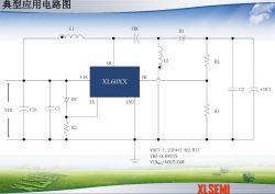
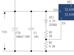
    The manufacturer of these XL6009 in the documentation on his website (but unfortunately not in DS) quite commonly recommends (also to his other bones) adding a zener on the EN pin, as a system against power supply from too low voltage, e.g.

    WARNING! Cheap step up / down converter - surprise ... XL6009

    where the value of the zener is roughly 0.8 of the supply voltage.


    But in places it also recommends a slightly more complex circuit (it is possible that in situations where it is not possible to precisely determine the voltage with a jumper from a typical series):

    WARNING! Cheap step up / down converter - surprise ... XL6009

    where it already more precisely calculates the resistors for specific desired on and off voltage of the converter, taking into account the threshold values for the EN input equal to 0.8 and 1.4V.
    For example, for the specific values of the elements in this picture, the calculated voltage of switching on the converter is 6.44V and switching off 5.7V:

    WARNING! Cheap step up / down converter - surprise ... XL6009


    But by the way, it seems to me that the struggle for the inverter to still work at 3.8V, for a cube with min. 5V power supply, additionally in the SEPIC configuration which has its own nuances, is asking for trouble.
  • #56 19075281
    Hobbysta Pasjonat
    Level 6  
    Hello, I have a similar problem, but it is a step up converter, correctly powered and properly loaded. The output voltage rises to 127V (while the output capacitors are 100V) when I turn the CC potentiometer to low values. Current regulation doesn't work at all. It has acted like this since the first start. I described the whole case in this topic, will anyone help? https://www.elektroda.pl/rtvforum/topic3750113.html#19062371
  • #57 19447664
    adam.eltra
    Level 12  
    I personally use these converters to power the varicaps in the radio tape recorder. Maja I provide 47nF capacitors on the input and output and 100nF between the first and last pins of the integrated circuit of this converter.

Topic summary

The discussion centers around the XL6009 step-up/down converter, highlighting a critical issue when operating below its specified input voltage range. Users report that while the converter functions well within the nominal parameters (3.8-30V input, 1.25-35V output), unexpected behavior occurs when the input voltage drops below 3.5V, potentially leading to dangerously high output voltages. Several participants note that this could damage connected devices, emphasizing the lack of under-voltage lockout (UVLO) protection in many cheap converters. Some users share their experiences with different models and configurations, suggesting that the design flaw may be common among similar products. Recommendations include using additional protective circuits and being cautious with low-voltage applications.
Summary generated by the language model.
ADVERTISEMENT