Hello all.
Today I would like to describe to you the HX3208 radio for self-assembly.

Such a set can be purchased on Aliexpress for $ 2.36 including shipping. I couldn't find this type of receiver on Allegro. In such a set you will find all the parts needed to assemble such a receiver, as well as the housing (almost all because you need two jumpers marked on the PCB as J1 and J2, but a piece of wire or a cut "leg" from the resistor from the set is enough to make it jumper). The radio is powered by two AAA batteries connected in series, which are not included in the set. You can see what we can find in the ordered package in the photos below.
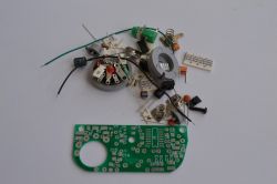
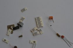
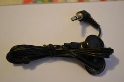
As you can see, we have a handful of parts, a housing and headphones, but no manual whatsoever.
In the description on the Aliexpress websites, sellers provide a list in which we can find the designation of the element on the board and the value of this element.
All in all, the elements are described in such a way that you can assemble this set without having a meter - as you can see in the photos, the capacitors are described in a similar way to the resistors, which is enough for their identification. People who know how to code the values of resistance or capacitance will have no problem identifying the part. However, not everyone has this knowledge, so especially for those who have a problem with it or do not have such knowledge, I have prepared a reworked list provided by sellers to identify parts. In addition, the parts include elements such as coils, which are not described, but in the descriptions of the sellers we will find information on how to recognize which coil has what inductance - this description is based on the number of turns of the coil.
Below is a reworked list to help you identify the parts.
This radio is based on a chip that has the designation CD9088CD. Sniffing around in the network, you can find information that this system is a copy of the Philips TDA7088T chip. I did not compare the documentation of these circuits, but looking at their outputs, they are the same, so it is possible that it is true. You can also find other chips such as YD9088 or SC1088, so it would seem that each copy has a different name.
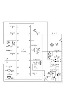
Below is a diagram of this radio.
Let's move on to assembly.
I don't know why, but they always write online and in tutorials to start with soldering the smallest elements. I always start by soldering integrated circuits.
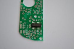
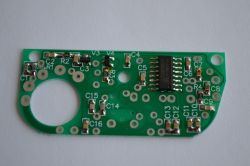
All SMD resistors and capacitors in this set are in the 6803 housing, which may be a problem for beginners, but there is a lot of space on the PCB and I think that you could easily solder elements in a larger housing, e.g. 1206.
After soldering all SMD components, I started soldering through-hole components.
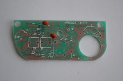
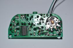
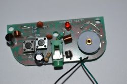
When soldering the L1 coil, I recommend cleaning its ends from insulating varnish to make sure that there will be a good contact after soldering.
We already have almost everything, now it is enough to solder the power cables to the places marked as "+" and "-" on the PCB, and solder the plates at their ends, which will do it for the battery contacts.
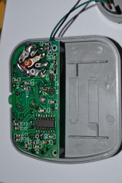
We put everything into the housing, the plate is screwed with one screw to the top of the housing.
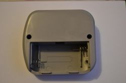
We put on the back of the housing. We screw the housings with two screws.
Screw the knob to the potentiometer.
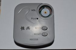
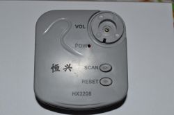
We put a cap on the knob.
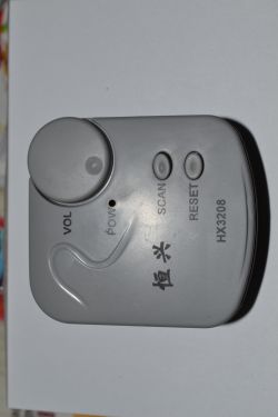
We put the battery in and we can start the radio. No tuning is required here.
We start the radio by turning the potentiometer to the right (the potentiometer has a built-in switch), which is announced by the red LED lighting up.
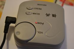
Turn the volume up by turning it to the right, decrease it by turning it to the left, turning it left to turn off the radio. The switch cuts off the power from the battery, so there is no question of any armed mode, so after turning off the radio does not draw power from the battery. The current drawn with a 3V supply is approx. 29mA. According to the sellers' descriptions, the radio operates in the voltage range from 1.8 to 3.5V. After my tests, I can say that the radio works properly up to a voltage of 2V, but it consumes 13mA at this voltage. I have not noticed,
so that the voltage level affects the picking quality of the radio station, you will notice that the supply voltage level affects the sound level.
After turning on its freshly assembled receiver, the radio started from the so-called kick and in the headphones I heard one of the most well received radio stations - Radio Maryja.
Our radio is equipped with two buttons described as "SCAN" and "RESET".
"SCAN" is used for scanning, pressing it switches to the next radio station, which is on a higher frequency, when we reach the end of the frequency range, this button stops turning on the next station. The "RESET" button is used to set the lowest frequency in this radio - it sets the beginning of the frequency range.
The only difficulty I encountered when assembling this radio was the polarization of the diode marked on the PVB as V1, i.e. BB910. In the depthsOn the Internet, I could not find documentation for a diode with this type of housing - TO-92. So that others will not have a problem with this, below is a drawing of what it should look like - you can also use photos from the assembly.
Radio assembled and launched, so now a few words on how it receives radio stations - as well as the quality of reception. What to expect from a radio for a few zlotys?
Some radio stations are heard with noise, sometimes it is enough to hold the radio in your hand to make the sound acceptable, others sound flawlessly. When receiving some radio stations, we may encounter a situation where the radio suddenly stops playing and then we only deal with silence in the headphones and we are only saved by pressing the "RESET" or "SCAN" button. At some stations it is quite common, which can change the mood we have at a given moment or even deepen it. Sometimes it is enough to move the radio one meter to another place and it's ok, and sometimes as a result of moving the radio in the headphones we hear another station.
Radyjko picks up better outside than in a house or apartment. In the metal hall, I found the station only after placing the radio against the metal leg of the table. For the test, I took them to the car and I can say that you can forget about enjoying the music while driving.
Summarizing, I can say that nowadays such a radio does not really exist, because today probably every "cell" after connecting headphones is able to receive radio stations. In addition, it should be mentioned here that from this radio we will only get the sound in MONO mode.
I can recommend this radio to people who are just entering the world of electronics, people who are starting their adventure with a soldering iron or those who enjoy a hand-built device more than a ready-made device.
I cannot say how long the batteries last, because I am not addicted to listening to music and I do not use this radio very often.
As a curiosity, I would like to add that the radio was completely soldered using an 8W USB sweat-powered soldering iron.
Below is a link to the description and review of the soldering iron used
https://www.elektroda.pl/rtvforum/topic3463963.html#17232011
Today I would like to describe to you the HX3208 radio for self-assembly.

Such a set can be purchased on Aliexpress for $ 2.36 including shipping. I couldn't find this type of receiver on Allegro. In such a set you will find all the parts needed to assemble such a receiver, as well as the housing (almost all because you need two jumpers marked on the PCB as J1 and J2, but a piece of wire or a cut "leg" from the resistor from the set is enough to make it jumper). The radio is powered by two AAA batteries connected in series, which are not included in the set. You can see what we can find in the ordered package in the photos below.


As you can see, we have a handful of parts, a housing and headphones, but no manual whatsoever.
In the description on the Aliexpress websites, sellers provide a list in which we can find the designation of the element on the board and the value of this element.
All in all, the elements are described in such a way that you can assemble this set without having a meter - as you can see in the photos, the capacitors are described in a similar way to the resistors, which is enough for their identification. People who know how to code the values of resistance or capacitance will have no problem identifying the part. However, not everyone has this knowledge, so especially for those who have a problem with it or do not have such knowledge, I have prepared a reworked list provided by sellers to identify parts. In addition, the parts include elements such as coils, which are not described, but in the descriptions of the sellers we will find information on how to recognize which coil has what inductance - this description is based on the number of turns of the coil.
Below is a reworked list to help you identify the parts.
| No. | Name | Value | Housing | Mark on the element | Marking on the PCB | Quantity |
| 1 | SC1088 | SOP-16 | CD9088CB | IC | 1 | |
| 2 | S9014 | SOT-32 | J6 | V3 | 1 | |
| 3 | S9012 | SOT-32 | 2T1 | V4 | 1 | |
| 4 | BB910 | TO-92 | BB910 | V1 | 1 | |
| 5 | LED | 3mm RED | V2 | 1 | ||
| 6 | Magnetic Bead Inductance | 4.7uH | dławik z ferytem | L1 | 1 | |
| 7 | Color Ring Inductance | 4.7uH | dławik ceramiczny | L2 | 1 | |
| 8 | Hollow Core Inductance | 78nH 8Round | 8 zwojów | L3 | 1 | |
| 9 | Hollow Core Inductance | 70nH 5Round | 5 zwojów | L4 | 1 | |
| 10 | Headset | 32ohm*2 | EJ | 1 | ||
| 11 | Resisitor | 15K | SMD | 153 | R1 | 1 |
| 12 | Resisitor | 150K | SMD | 154 | R2 | 1 |
| 13 | Resisitor | 1.2K | SMD | 122 | R3 | 1 |
| 14 | Resisitor | 5.6K | SMD | 562 | R4 | 1 |
| 15 | Metal Film Resistor | 680ohm | R5 | 1 | ||
| 16 | Potentionmeter | 51K | RP | 1 | ||
| 17 | Capacitor | 2.2nf | SMD | 223 | C1 | 1 |
| 18 | Capacitor | 0.1uf | SMD | 104 | C2 | 1 |
| 19 | Capacitor | 220pf | SMD | 221 | C3 | 1 |
| 20 | Capacitor | 0.33nf | SMD | 331 | C4 | 1 |
| 21 | Capacitor | 0.22nf | SMD | 221 | C5 | 1 |
| 22 | Capacitor | 3.3nf | SMD | 332 | C6 | 1 |
| 23 | Capacitor | 180pf | SMD | 181 | C7 | 1 |
| 24 | Capacitor | 680pf | SMD | 681 | C8 | 1 |
| 25 | Capacitor | 68nf | SMD | 683 | C9 | 1 |
| 26 | Capacitor | 0.1uf | SMD | 104 | C10 | 1 |
| 27 | Capacitor | 22nf | SMD | 223 | C11 | 1 |
| 28 | Capacitor | 0.1uf | SMD | 104 | C12 | 1 |
| 29 | Capacitor | 470pf | SMD | 471 | C13 | 1 |
| 30 | Capacitor | 33pf | SMD | 33 | C14 | 1 |
| 31 | Capacitor | 82pf | SMD | 82 | C15 | 1 |
| 32 | Capacitor | 0.1uf | SMD | 104 | C16 | 1 |
| 33 | Ceramic Capacitor | 3.3nf | 332 | C17 | 1 | |
| 34 | Electrolytic Capacitor | 100uF | 100uF | C18 | 1 | |
| 35 | Ceramic Capacitor | 22nf | 223 | C19 | 1 | |
| 36 | Cable | D0.8*6mm | 2 | |||
| 37 | Box | 1 | ||||
| 38 | Potentiometer knob | 2 | ||||
| 39 | Button | 2 | ||||
| 40 | Battery spring clip | Sets 3pcs | 1 | |||
| 41 | Switch | 6x6mm | S1, S2 | 2 | ||
| 42 | Headphone jack | D3.5mm | XS | 1 | ||
| 43 | Screew / Nut | Several |
This radio is based on a chip that has the designation CD9088CD. Sniffing around in the network, you can find information that this system is a copy of the Philips TDA7088T chip. I did not compare the documentation of these circuits, but looking at their outputs, they are the same, so it is possible that it is true. You can also find other chips such as YD9088 or SC1088, so it would seem that each copy has a different name.
Below is a diagram of this radio.

Let's move on to assembly.
I don't know why, but they always write online and in tutorials to start with soldering the smallest elements. I always start by soldering integrated circuits.


All SMD resistors and capacitors in this set are in the 6803 housing, which may be a problem for beginners, but there is a lot of space on the PCB and I think that you could easily solder elements in a larger housing, e.g. 1206.
After soldering all SMD components, I started soldering through-hole components.


When soldering the L1 coil, I recommend cleaning its ends from insulating varnish to make sure that there will be a good contact after soldering.
We already have almost everything, now it is enough to solder the power cables to the places marked as "+" and "-" on the PCB, and solder the plates at their ends, which will do it for the battery contacts.
We put everything into the housing, the plate is screwed with one screw to the top of the housing.

We put on the back of the housing. We screw the housings with two screws.

Screw the knob to the potentiometer.


We put a cap on the knob.

We put the battery in and we can start the radio. No tuning is required here.
We start the radio by turning the potentiometer to the right (the potentiometer has a built-in switch), which is announced by the red LED lighting up.

Turn the volume up by turning it to the right, decrease it by turning it to the left, turning it left to turn off the radio. The switch cuts off the power from the battery, so there is no question of any armed mode, so after turning off the radio does not draw power from the battery. The current drawn with a 3V supply is approx. 29mA. According to the sellers' descriptions, the radio operates in the voltage range from 1.8 to 3.5V. After my tests, I can say that the radio works properly up to a voltage of 2V, but it consumes 13mA at this voltage. I have not noticed,
so that the voltage level affects the picking quality of the radio station, you will notice that the supply voltage level affects the sound level.
After turning on its freshly assembled receiver, the radio started from the so-called kick and in the headphones I heard one of the most well received radio stations - Radio Maryja.
Our radio is equipped with two buttons described as "SCAN" and "RESET".
"SCAN" is used for scanning, pressing it switches to the next radio station, which is on a higher frequency, when we reach the end of the frequency range, this button stops turning on the next station. The "RESET" button is used to set the lowest frequency in this radio - it sets the beginning of the frequency range.
The only difficulty I encountered when assembling this radio was the polarization of the diode marked on the PVB as V1, i.e. BB910. In the depthsOn the Internet, I could not find documentation for a diode with this type of housing - TO-92. So that others will not have a problem with this, below is a drawing of what it should look like - you can also use photos from the assembly.
Radio assembled and launched, so now a few words on how it receives radio stations - as well as the quality of reception. What to expect from a radio for a few zlotys?
Some radio stations are heard with noise, sometimes it is enough to hold the radio in your hand to make the sound acceptable, others sound flawlessly. When receiving some radio stations, we may encounter a situation where the radio suddenly stops playing and then we only deal with silence in the headphones and we are only saved by pressing the "RESET" or "SCAN" button. At some stations it is quite common, which can change the mood we have at a given moment or even deepen it. Sometimes it is enough to move the radio one meter to another place and it's ok, and sometimes as a result of moving the radio in the headphones we hear another station.
Radyjko picks up better outside than in a house or apartment. In the metal hall, I found the station only after placing the radio against the metal leg of the table. For the test, I took them to the car and I can say that you can forget about enjoying the music while driving.
Summarizing, I can say that nowadays such a radio does not really exist, because today probably every "cell" after connecting headphones is able to receive radio stations. In addition, it should be mentioned here that from this radio we will only get the sound in MONO mode.
I can recommend this radio to people who are just entering the world of electronics, people who are starting their adventure with a soldering iron or those who enjoy a hand-built device more than a ready-made device.
I cannot say how long the batteries last, because I am not addicted to listening to music and I do not use this radio very often.
As a curiosity, I would like to add that the radio was completely soldered using an 8W USB sweat-powered soldering iron.
Below is a link to the description and review of the soldering iron used
https://www.elektroda.pl/rtvforum/topic3463963.html#17232011
Cool? Ranking DIY


