logo elektroda
logo elektroda
X
logo elektroda

Hilti C4/36-350 Charger Issue: Green LED Flashing Every 2s, Battery Not Charging

rsv6 110928 225
ADVERTISEMENT
Treść została przetłumaczona polish » english Zobacz oryginalną wersję tematu
  • #211 21480493
    krakarak
    Level 42  
    And this is a decent, tester-based description of the condition of individual cells.... Measuring the battery with a dash and a second hand....

    Mate, take the pack out of the case, disconnect the electronics from the cells and with a tester that measures the impedance of the cells do their analysis.
    Do you have such a tester? If not then, unfortunately, you should put it in the hands of someone who owns one and has the knowledge of how to measure individual cells, how to interpret the result (good-bad), owns a meter and will take measurements on the electronics board, can familiarise themselves with the battery charge control system (BMS).
    In my opinion, here no one will be able to solve your problem remotely, just based on the number of glowing dashes. At least I am not aware of such a method to locate the problem in the package.
  • ADVERTISEMENT
  • #212 21494643
    Lucbbs
    Level 1  
    hello,
    would it be possible to know the voltage and functions of the different pins on the output connector?,

    thanks
  • #213 21512301
    spicter
    Level 23  
    Welcome.

    I have an identical patient on my table.
    I have taken some measurements around the MIP2M2.

    ZD17 shorted - I replaced with a 0.5W 15V Zener diode.

    1. 5.83V
    4. 15.03 V
    5. 309 V
    8. 0.89V

    Sometimes the charger will start with the LED active - then VCC is exactly 13.09V

    Does this behaviour disqualify the MIP2M2?
  • ADVERTISEMENT
  • #214 21513310
    manuelconso98
    Level 2  
    Hello,
    I have a faulty Hilti C4/36-350 that has fallen from a high place. Firstly, I noticed that the big capacitor was gone, then I replaced it but still no signal of life. No LED flash at all.
    I have checked the voltage on the transformers and I measure correctly the 300V from the bridge rectifier on the first big transformer, but on the small one I have no tension at all, only 0.5/0.6V.
    The diode D5 and the Zener ZD13 are fine, and before the ZD13 I have 300V, but after nothing.
    I noticed that when it's plugged to the AC, I measure between pin 5 and 7 of the MIP2M2 static 59kOHM, that from the datasheet found in this forum should be the Source and Drain of the MOSFET that should be swinging from close to open to drive the small transformer (am I correct?), maybe the MIP2M2 is gone? or is it normal?
    All around the low power board I have no voltage, so none of the chips are ON, neither the L6599AD.
  • #215 21516473
    marchakoleg911
    Level 3  
    Hello!
    What could be wrong with the charger? The LED lights up, no response to inserting the battery, the fan also does not switch on
  • #216 21517207
    Marko121
    Level 17  
    >>21516473 disconnect the diode so that it does not light up will be complete in unresponsive :)

    pardon the pun , but if you don't have any experience in measurement and service , you won't fix such a complicated inverter , and don't rummage around in there because you will break even worse .
  • #217 21517294
    krakarak
    Level 42  
    >>21516473 and did you read the post above yours?.... Do...

    Also - all your posts are of the same content and in this topic. Are you stammering or are you mocking?
  • #218 21523710
    spicter
    Level 23  
    My charger repaired. In addition to the faulty Zener diode, the 400V capacitor and components around the transformer had cold solders.

    Sometimes (as I wrote above) the green diode did not light up or was flickering.
    Following this lead it was possible to remove the fault.
  • ADVERTISEMENT
  • #219 21527161
    vkudryakov
    Level 3  
    >>20872003 Hello! Can you measure the voltage on LED100? My LED is 12.6 V and it glows and smokes. Why can the voltage on C111 be 12.6 V? And type/nominal/datasheet/marking code Q127 and Q123
  • #220 21528235
    manuelconso98
    Level 2  
    Hi,
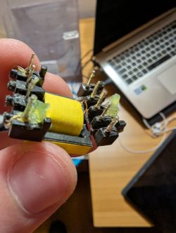
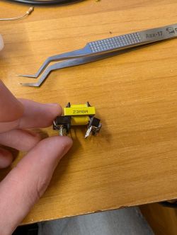
    I found the problem described in the previous post, after the fall the small transformer probably took a hit and broke the primary wires. The problem is that I can't find anything online by searching for the code reported on the side "Z3M8A", and I couldn't even find a transformer with the same pin number and positions.
    Do You have any information on this transformer?
    Thanks
    Electronic transformer held between fingers in front of a laptop on a desk.
    Switching transformer held between fingers on a wooden desk, tweezers nearby.
  • ADVERTISEMENT
  • #221 21551803
    vkudryakov
    Level 3  
    My diagnostics revealed a resistance of 30 Ohm between the Vcc and Vss pins of the MCU freescale mc9s08ac48 32pin. Can someone measure the resistance on your hilti c4/36-450? Is it possible to read the firmware from this MC?
    For those who may need help - with such a malfunction, the divider chain R111-R112 and ICU101 does not work. As a result, the optocoupler PC5 is completely open and instead of 8.4 V on the low side of t2 c111 there is 12.6 V
  • #222 21555401
    stijepicmladen
    Level 2  
    Trying to repair, changed L6599 just to find out that command for starting comes from PC4. Everything seems ok, steady green LED, 8.4V present, 11.5V present but no start. After connecting my bench power supply to imitate output of main power supply, system starts, relay clicks, fan starts. battery charging. If I short BCP54 that starts L6599 there is no green LED. Any idea?
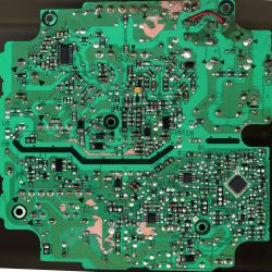
    Close-up of a green printed circuit board (PCB) with various electronic components and tracks.
    This is 2400dpi scanned PCB on EPSON 1680. It can be useful do download full resolution image.
  • #223 21558759
    stijepicmladen
    Level 2  
    Did a bench supply of l6599, 12.5v vcc, resistor divider to pin 7 for 2v, simulating line voltage present. Now scope shows triangle wave on pin 3, outputs working. Still thinkering.
  • #224 21567365
    dariusz_21
    Level 23  
    if anyone is looking for mip2m2 and 1r0 resistors, I have them in stock and am willing to share
  • #225 21585185
    rademeness
    Level 11  
    @stijepicmladen you have a 39 kΩ R185 resistor eaten and a 47 kΩ resistor next to it, replace and it should start.
  • #226 21614328
    odzkpm2011
    Level 1  
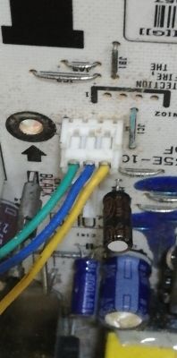
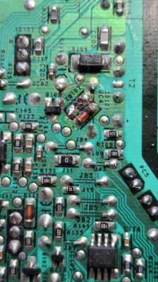
    Greetings to everyone at elektroda.com from Havana. I'm trying to repair a HILTI charger. The electrolytic capacitor C3 (390uF/400 Volts) has 325 Volts. Pin 5 of IC2 (MIP2M) has 325 Volts, and pin 4 has 16 Volts. Transistor Q5 is in perfect condition. The cathode of D104 has 12.5 Volts. What voltage should there be across the green, blue, and yellow wires that connect to the battery? I've measured all the Zener diodes, and they're fine. Thank you very much, and best regards from Cuba.
    Daniel
    HILTI charger circuit board with several electronic components, wires, and marked measurement points.
    [img-0]

Topic summary

The Hilti C4/36-350 charger exhibits a green LED flashing every 2 seconds and fails to charge batteries, with no response upon battery insertion. The issue often relates to faults in the power supply section, including damaged components such as IC1 (L6599AD), IC2 (MIP2M2), transistors Q3 and Q4 (12NM50ND or STP12NM50FP), and various diodes and resistors (notably zener diodes ZD16, ZD17, ZD14, and Schottky diode D9). Common failures include burned PCB tracks, short circuits in power transistors, and damaged zener diodes causing voltage instability. The L6599AD chip controls the power supply with a recommended supply voltage between 9V and 16V, often regulated via transistor Q5 (BCP54 or BSS138N). The MIP2M2 IC manages the main converter output, typically providing around 13V on pin 4 and high voltage (~320V) on pin 5. Faulty optocouplers (e.g., PC3, PC4, VO615A or PC817 replacements) can also cause shutdowns after a few seconds of operation. Repair strategies include checking and replacing damaged zener diodes (notably ZD16 with correct 5.1V rating), transistors, resistors (R31, R42, R51, R24, R30, R33), and ensuring no short circuits on IC pins. Use of a series test lamp during power-up is recommended to prevent further damage. Some users report success replacing L6599AD with L6599D variants and substituting original insulated MOSFETs with equivalents using thermal insulation. The charger’s complex multi-stage power supply and feedback circuits require careful diagnosis, with schematics and component datasheets (e.g., L6599AD, MIP2M2) aiding troubleshooting. Persistent issues often stem from damaged feedback loops, unstable supply voltages, or repeated component failures due to underlying faults. Community efforts include sharing partial schematics, component values, and repair experiences to facilitate effective restoration of this widely used charger model.
Summary generated by the language model.
ADVERTISEMENT