logo elektroda
logo elektroda
X
logo elektroda

Hilti C4/36-350 Charger Issue: Green LED Flashing Every 2s, Battery Not Charging

rsv6 110928 225
ADVERTISEMENT
Treść została przetłumaczona polish » english Zobacz oryginalną wersję tematu
  • #151 20872003
    DRAZEK87
    Level 15  
    PiterSen151 wrote:
    Slightly lower voltages than those in the diagrams


    What is the AC voltage in the socket where you are measuring?

    PiterSen151 wrote:
    ... I also replaced the MIP but it didn`t help. Now there is no voltage on C3 (the voltage jumps to 2V), the charger turns on for a fraction of a second and then turns off over and over again.


    and I am already writing to you what is required for MIP to work, the condition is a constant voltage on C3 within 320V! it must always be there, and it will only be there when the CR1 triac works; you can observe that before it, from the bridge side, you will have an unstable voltage of about 220-240 ACV, and behind it, from the C3 side, with various fluctuations, sometimes 2v, sometimes 150-170v, and sometimes I even noted above 200v and that`s why the charger wants to surprise, sometimes LED100 will flash and it will reset.

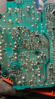
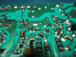
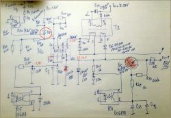
    The solution to your problem is to find the damaged element(s) in the area of the Q7 system (double transistor = BC817DPN) or to replace the damaged system itself; For future generations, I will make it easier for you and provide the correct voltages in this system, see photo; you need to get about 0.8v on pin 1 of the PC1 optocoupler that starts the triac. As an interesting fact, I would like to add that the capacitor marked in red, with unknown element numbering on the board, is responsible for the start of the triac and its damage, and I have encountered such a situation, which will cause the system to reset and produce the effects that you describe. Since the element was damaged and there was no opportunity to measure it earlier to find out its values, I tested 100nF for 50v and hit the mark, a constant 320v appeared on C3 and Ic2 worked, LED100 lit up. Then I took measurements and marked them in green on paper, so you see.
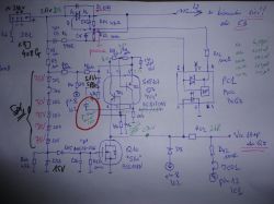
    Hand-drawn electrical diagram with highlighted components and annotations.

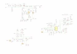
    As for your measurements, they are normal and most of them agree with what I have already described, although I am slightly concerned about the 285v voltage on pin 5 of the Ic2 system; apply AC voltage from the socket and everything will be explained to us. As for the voltage on Ic1, I have not previously measured it on a working charger and I will work on it and it will be updated. As a novelty, I drew another sector from the microcontroller side, specifically from the T2 transformer, where we have 8.34v on C111; it will be useful to others and it also gives voltage. I mark pin 1 on PC3, we have 4.77v; and on pin 2 3.66v and beyond there is a line to the Ic103 pin 7 to the LM358 operational amplifier; which is responsible for the protection by giving the appropriate signal to the microcontroller; and after checking, it turns on the main converter via the PC3 optocoupler. Ic103 operational amplifier is also responsible for measuring the current through the R105 shunt. In the next statement I will present a detailed diagram of this area of the system as I am finishing drawing the next sector; That`s it for today. Good luck repairing your own equipment.
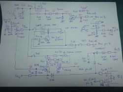
    Hand-drawn schematic of an electronic circuit on white paper.
  • ADVERTISEMENT
  • #152 20873024
    PiterSen151
    Level 10  

    Welcome back. Thanks for the answer. Info that I have now:
    - In the second charger that I have on my wallpaper, there is clearly a short circuit somewhere in the triac.
    - Q3, Q4, and IC1 are desoldered as a precaution, the 300 V does not even reach IC2, it disappears along the way.
    - 99% of the lower voltages are due to the fact that I make all the measurements behind the bulbs (they are approx. 40W in parallel) and on the bridge there is approx. 210V but it drops to 190V when the triac is triggered (every approx. 0.5 sec), the current from I won't be able to measure the network because I have a clamp meter and it shows a momentary low current, but it probably won't catch the pins.
    - The triac triggers, but as a result of this short circuit, the voltage in the circuit drops and it turns off before any damage occurs (because the voltage on the gate also drops).
    - When I put a 500W halogen lamp in series, the 1R resistors R24 and R30 blew again, there was a slight crackle on the side of the through-hole elements and there was a slight smell of burning (I had this happen twice) but no damage was visible and the C3 capacitor was charged after burning them.
    - Once, instead of SMD, I soldered through-hole resistors instead of R24, 30, and 33, when they were turned on directly without bulbs, they looked like Christmas tree lights and got lit.
    - The board heats up around the triac to about 35-40 degrees (probably from the short-circuit current), the rest is cool.
    - As a preventive measure, I replaced Q10, Q7 (the old ones were probably ok), this one has 7 V and jumping voltages, probably around 0.8 V as I remember.
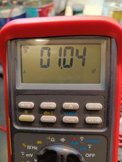
    - After soldering, I checked these unknown elements: the unmarked zener diode next to Q7 has 6.9 V (the same in the second charger - I checked the T-7 LCR, is it reliable?) and the 1uF capacitor (it's already a Brymen 859S, even though I installed it in working order new, I only had 10V in this housing).
    - I don't know why, but something is happening in the branch with resistors R15, 16, 17, 1.4M each - after shooting, I couldn't measure them (opening), after desoldering, they have their own 1.4M, just in case, I inserted new ones (I had 1.5M in this housing) and they measure correctly, but nothing has improved.
    - These blue elements can cause short circuits when 220V is turned on? or is it rather a transformer (after tap 9)? how to examine it further, the small piece has been checked and it looks fine.
    - It's a bit slow for me because I do it in the evenings after work as an "amateur", I have a lot of these chargers at work and previously I gave it to a service center that makes power tools for us and they gave it to some electronics technician for the chargers, but when I saw what he was doing in them (wired fuses, a few it went to the scrapyard and as I see, the parts are available, I just need more time) since in winter I have more time, I took matters into my own hands and I'm slowly figuring it out.
    - Milwaukee is waiting in line :) Apparently it's impossible to find and was supposed to be scrapped, for now, I'll learn how to use it and check the other one myself. We are slowly moving away from HILTI because they have become extremely expensive and break down often, but I still have some of them and I ordered parts from TME and some from China, so this will be the base for repairs.
  • #153 20873167
    DRAZEK87
    Level 15  
    PiterSen151 wrote:
    1R resistors R24 and R30 blew again


    If you have burnt the above elements, there is a 99% chance that you have damaged Ic2, i.e. MIP, check whether you have a short circuit or low resistance between pin 5 and 7; Before you install a new system, carefully check the small details around it; in particular zener diodes and Q5; without keys and Ic1, you need to recover 13v so that the LED lights up; and only then will we deal with the main converters; I don`t remember now whether the triac will work properly without Ic2; but I`ll check it during the day as soon as I`m in the workshop; I will deliberately desolder a functional MIP and measure the voltage on C3 because that`s what happens; that I have a charger that currently does not have soldered keys and L6599AD.
  • #154 20873381
    PiterSen151
    Level 10  
    Each post is a bit of new knowledge. It will probably be this, it is around 30R now and the one desoldered is 60R, so both were dead. I didn`t know how to check them, thanks for your help. The delivery is just coming from China and will probably arrive in the first days of January, TME does not have them. The charger has been lying around for a month, so it will wait another 2 weeks, right now there is more rest for the holidays and it is not urgent.

    PS: after desoldering MIP2, there is no longer a short circuit (there was a short circuit between 5 and 7, which is ground due to low resistance), the capacitor has 320 V, and there is already voltage on the pin where pin 5 is supposed to be.
  • #155 20873559
    DRAZEK87
    Level 15  
    PiterSen151 wrote:
    there it is around 30R now and on the desoldered one it is 60R, so both were dead


    both crap! I will make it easier for you to check the MIP before you send another piece;

    the first thing you need to do when the charger is dead is to check whether the DC voltage on the C3 network capacitor is within 320v; if it is missing, remove the MIP, probably the keys and Ic1 will also be removed, I recommend soldering these elements as a preventive measure;

    I am answering the question from the previous issue: if we remove the MIP, will there be a voltage of 320v on C3; I soldered the system; I checked and the answer must be 320v! if it is missing without MIP, then, as I wrote earlier, there is damage around Q7, Q10, the PC1 optocoupler and finally the CR1 triac;

    when we have the correct voltage on C3 and the MIP has been desoldered, we check the voltages on the board on individual pads relative to ground and they should be:
    1. 0.03v
    2. none
    3. 0.03v
    4. 0.54v
    5. 321v!!!
    6. missing leg
    7. mass
    8. 1/08v

    you can additionally call the meter and if you put a minus probe to GND; and a positive probe to pad 5, the measurement will be within 1770; no measurement for other pads; however, if we reverse the probe to GND and give a positive one, and to the individual pads a minus one, then there will be 538 on pin 1, 716 on 3, and none on 2/4 and 5; 6 is gone; 7 short circuit, and pin 8 will indicate the moment of measurement and will rapidly increase out of range; this way we have a chance that the album is probably OK

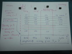
    now it`s time for our MIP; I present my notes that I made for easy checking of the system, see photo

    Photo of notes with measurement results for electronic circuits.

    we have 4 layouts; 2 on the left are new; 3 soldered, probably functional, but from a dead charger in which the damage was in another sector, and the system was replaced as a preventive measure; 4th system is a dead body blown up;

    by calling the meter on individual pins, we will get results similar to those in the table, I mark the positive probe to pin 7 GND; and we check with the minus probe; the resistance between pins 7 and 5 must be high, close to 1MR; low resistance or a total jumper is an instant failure, and even to other pins disqualifies the competitor; that`s all the width in measurements for today; now "PiterSen151" you can carefully check your circuits and board and check whether you have 320v on C3; bajo

    HEALTHY AND MERRY CHRISTMAS
  • ADVERTISEMENT
  • #156 20898826
    PiterSen151
    Level 10  

    Hello. I bought another 2 pieces. In one, MIPM2 and 3x1R resistors were enough, and in the other, L6599AD, MIPM2 and 3x1R resistors. I spent a lot of time working on the second one, I was looking for the 13V voltage on the 12th leg of the L6599AD and thanks to the new diagrams (thanks for sending it), I finally figured out that the processor sends a signal to the optocoupler and controls Q5 only after inserting the battery! Both systems come straight from China, so you can save a little, and so far they work. Milwaukee is also made, it's much easier there because there is no varnish, only some liniment, so it's easier to measure and the elements themselves are probably 1/3 of what they are in Hilti. There, the default option was TOP261EN and an additional PC817 optocoupler.
  • #157 20916344
    Brutal123
    Level 14  
    Someone suggest C47 what value ? - I think it is from it went fire until it burnt the casing . Low resistance on IC1 power supply . Something else to replace at the beginning ? Symptom flashing green LED after replacing the fuse .
  • #158 20918721
    DRAZEK87
    Level 15  
    Brutal123 wrote:
    Can anyone tell me what the value of C47 is? - the fire probably came from it and soot filled the casing. Low resistance on power supply IC1. Anything else to mention first? Symptom: green diode flashes after replacing the fuse.


    I`ll tell you if you tell me where to look for it on the disc, take a photo and mark this element...
  • #160 20920577
    ini1995
    Level 1  

    Brutal123 wrote:
    Someone suggests C47, what value? - I think it is from when it caught fire until it burnt the casing. Low resistance on IC1 power supply. Is there something else to replace at the beginning? The symptom is a flashing green LED after replacing the fuse.


    Electronic circuit schematic with various components.
  • #161 20924505
    Brutal123
    Level 14  
    Thank you very much for the diagram.
  • #162 20924641
    DRAZEK87
    Level 15  
    Brutal123 wrote:
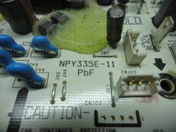
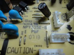
    The above board is probably marked NPY335E-11, see photo.
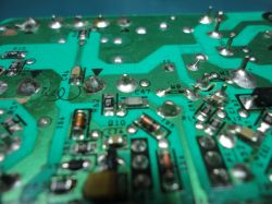
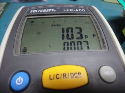
    Close-up of a printed circuit board labeled NPY335E-11. Close-up of a printed circuit board with labeled electronic components, such as capacitors and resistors. LCR meter displaying 103 pF.
    Therefore, C47 has a value of 100pF, and the series resistor R62 has a value of 47R and I assume that the whole creates the so-called extinguisher;

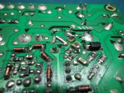
    The above elements are not present on the board number NPY335E-8; the rest are slightly moved compared to the previous model.
    Close-up of a printed circuit board marked NPY335E-8 with various electronic components. Close-up of a circuit board with visible electronic components, including capacitors and resistors.

    Please measure the C46 capacitor, we have it right next to C47 and it connects to the R60 resistor, which has 47R, creating another snubber. In my case it is measured as 4.7nF even though it is already damaged, but you can see that it is higher than C47 and has a slightly different color. Same 1206 housing. I would like to replace it with a new one.
    Image of a circuit board with highlighted capacitor C46.
  • #163 20941868
    Brutal123
    Level 14  
    C46 is also 4.7n in my case. The charger is still not done. Replaced IC1 ZD6 C47. The diode flashes like it used to. Anyone else have any ideas? or would you like to take care of it?
  • #164 20942007
    PiterSen151
    Level 10  

    If ZD6 was dead, was Q 10 intact? I guess what remains is to look for tensions, see if they exist and where they disappear. MIP-M2 gives 13 V with a battery installed?
  • #165 20951204
    jan262
    Level 5  

    Hello, does anyone have the value of capacitor C5? There is only a post here mentioning the value of 1nF, which may be a measurement error.
  • ADVERTISEMENT
  • #167 20955279
    DRAZEK87
    Level 15  
    PiterSen151 wrote:
    - I don`t know why, but something is happening in the branch with resistors R15,16,17, 1.4M each - after shooting, I couldn`t measure them (opening), after desoldering, they have their own 1.4M, just in case, I inserted new ones (I had 1 .5 M in this housing) and they measure correctly, but nothing has improved


    I checked and confirm that the above resistors will not measure correctly in the circuit; at least one should be desoldered and then measured, they should be 1.4MR marked as 1404 and purchasing them in a 1206 housing is a problem because they are not available as standard; we have 1.3MR or 1.5MR

    as for C5, I once measured it in a damaged charger, I had 730pF but I found that the measurement was incorrect and I put 1nF and the charger worked with it correctly;
  • #168 20958818
    goranz
    Level 2  

    I've had good luck with these chargers so far. When they didn't give any signs, it was either a 5A fuse or a MIP2M2 with three 1-ohm SMD resistors leading to it. After replacing it, if the LED goes on and off, I'd replace the L6599AD and the charger would work normally. Thanks for this thread and the electrical schematics.
  • #169 21011809
    brazdasand
    Level 1  

    Welcome everyone! Does anyone have information about the C4/36-350 charger connector? at which point what should be measured and what are its functions?
  • #170 21073401
    zamir0709
    Level 1  

    >>20920577 R24, R30, R33 and R38 burned down. Help, where is the cause of the breakdown? What should I check first?
  • #171 21074116
    PiterSen151
    Level 10  

    First check the resistance on MIP2M2 between 1st VDD and 4th VCC - it often drops.
    .
  • #172 21095630
    radiosnavigaciou
    Level 2  

    Please if the diode type is D8? Electronic schematic with a red marking around diode D8.

    Added after 5 [minutes]:

    >>20920577 Please, do you have it in a better resolution?
  • #173 21099242
    PiterSen151
    Level 10  

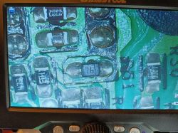
    Close-up of a circuit board with components, including a marking 76 on one part.
    I think this is the one, you can faintly see the signature and the marking is 76, supposedly BAS70-06 but it should be in a SOT-23 housing. I have no experience with these codes so maybe someone else can help.
  • #175 21133593
    blisk2000
    Level 1  
    Hi,

    I like to say hello to everyone on this forum!

    I have a problem with this type of charger.
    When I connect a battery all seems to be ok, and aku is charging. But after a few seconds, it stops with charging and all leds on battery are off.
    I checked battery - it is ok, it can be charged on on other charger. So I am sure that the problem is on this specific charger.
    Here is a link of video:


    Any idea what can be faulty?
    Thank you very much in advance!
    Best regards, Zdenko.
  • #176 21133720
    goranz
    Level 2  
    a large part of this discussion is dedicated to this kind of failure, if you're lucky then it's only L6599ad, if you're unlucky then there's a bunch of defective parts around it
  • #177 21195083
    IOANO
    Level 1  
    hello ,
    I tried in every way but I can't see very well the scheme of the user ,,InI1995,, in post 161. I need your help.
    I downloaded to my computer but the picture is not clear.
    Best regards ,
    IOAN
  • ADVERTISEMENT
  • #178 21198836
    DRAZEK87
    Level 15  
    blisk2000 wrote:
    After connecting the battery everything seems ok, the battery charges. But after a few seconds it stops charging and all the LEDs on the battery go out.
    I checked the battery - it is ok, it can be charged on another charger. So I am sure that the problem lies with this particular charger.


    just because you put the battery on another charger doesn't mean it's not bad, tell me how long you charged the battery on a good charger and at what level you started; because I had such a problem and it turned out that one of the cells in the battery was damaged after disassembly, visible flooding which caused the battery to charge quickly and actually mislead the charger, which in effect ended up stopping charging at, for example, 2 or 3 bars, removing it and waiting a while to put it back in caused charging again, say within 5-10 minutes and stopping; you should discharge the battery to the minimum and only then put it back in and observe what happens to it as long as it charges on a good charger then you will confirm that you have a good battery and the 5 min test will not add anything to the fact that the fault lies with the charger... on these models when the cells die the symptoms are that the battery lands at 2 bars and sometimes shuts down at three, it depends on the degree of wear of the cells or the failure of one of them, thats all for today. cheers
  • #179 21215535
    Przemo_997
    Level 1  
    Hi.

    I bought a second C4/36-350 recently, but it disconnects charging after 10 seconds, with IC2 someone fiddled with as you can see the solder marks. After all these years, has anyone figured out what sits on these PCBs (apart from IC1 and everything related to it)?

    As a consolation, I have a working piece next to me 😅 The meter is there so I can measure, just a question of what....

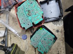
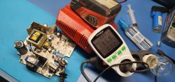
    Two disassembled electronic devices on a workbench showing PCBs.
  • #180 21224296
    h3c4
    Level 15  
    I'll give my tip :

    if the green LED is on, after inserting the battery after 5-10 it switches off charging i.e. the main inverter generating the voltage is not working - you need to replace the L6599AD/ L6599D chip

    Before :


    .


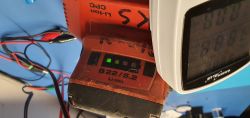
    After : Disassembled battery charger on a workbench with an energy meter displaying voltage. Green LED is lit on the Li-Ion B22/5.2 charger. .

Topic summary

The Hilti C4/36-350 charger exhibits a green LED flashing every 2 seconds and fails to charge batteries, with no response upon battery insertion. The issue often relates to faults in the power supply section, including damaged components such as IC1 (L6599AD), IC2 (MIP2M2), transistors Q3 and Q4 (12NM50ND or STP12NM50FP), and various diodes and resistors (notably zener diodes ZD16, ZD17, ZD14, and Schottky diode D9). Common failures include burned PCB tracks, short circuits in power transistors, and damaged zener diodes causing voltage instability. The L6599AD chip controls the power supply with a recommended supply voltage between 9V and 16V, often regulated via transistor Q5 (BCP54 or BSS138N). The MIP2M2 IC manages the main converter output, typically providing around 13V on pin 4 and high voltage (~320V) on pin 5. Faulty optocouplers (e.g., PC3, PC4, VO615A or PC817 replacements) can also cause shutdowns after a few seconds of operation. Repair strategies include checking and replacing damaged zener diodes (notably ZD16 with correct 5.1V rating), transistors, resistors (R31, R42, R51, R24, R30, R33), and ensuring no short circuits on IC pins. Use of a series test lamp during power-up is recommended to prevent further damage. Some users report success replacing L6599AD with L6599D variants and substituting original insulated MOSFETs with equivalents using thermal insulation. The charger’s complex multi-stage power supply and feedback circuits require careful diagnosis, with schematics and component datasheets (e.g., L6599AD, MIP2M2) aiding troubleshooting. Persistent issues often stem from damaged feedback loops, unstable supply voltages, or repeated component failures due to underlying faults. Community efforts include sharing partial schematics, component values, and repair experiences to facilitate effective restoration of this widely used charger model.
Summary generated by the language model.
ADVERTISEMENT