logo elektroda
logo elektroda
X
logo elektroda

Hilti C4/36-350 Charger Issue: Green LED Flashing Every 2s, Battery Not Charging

rsv6 107340 224
ADVERTISEMENT
Treść została przetłumaczona polish » english Zobacz oryginalną wersję tematu
  • #31 17713122
    rsv6
    Level 13  
    The slingshot itself fails ..
  • ADVERTISEMENT
  • #32 17727610
    NNTFD
    Level 11  
    I sold the Prock from a different charger. Further the same - turning off after 5 seconds.
    Has anyone had a problem with a transformer or an operational amplifier?
  • ADVERTISEMENT
  • #33 17727634
    rsv6
    Level 13  
    I know that there was a zener diode that made a short circuit after damage. But I don't remember anymore because it was a long time ago ...
  • ADVERTISEMENT
  • #34 17845419
    elcarcar
    Level 2  
    Welcome friends.
    I found a short Zener diode DZ16 in this charger, does anyone know its value?
    Thank you
  • #35 17847790
    NNTFD
    Level 11  
    If it's the diode at the FET transistor is 15V. Most of the zippers on this board are at 15V.
  • #36 17848361
    elcarcar
    Level 2  
    thanks, the zener anode is at GND of the main capacitor and the cathode connects to the mosfet source
  • #37 17896888
    updown5678
    Level 2  
    U1 --- (OPEN) L6599AD
    J3 --- (OPEN) 0R
    D9 --- (SHORT) B4
    ZD16 --- (OPEN) ???
    Q3.Q4. (OPEN) 12NM50
    R51 --- (OPEN) 10R

    Does anyone know how to fix this?

    Does anyone know about unknown part model?

    If the above parts are replaced

    Also pay attention to which parts are being measured

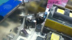
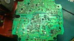
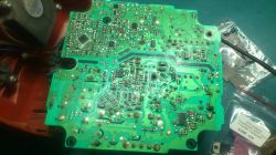
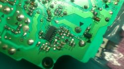
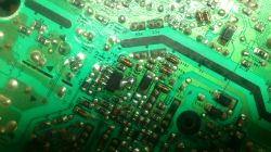
    I also put the photos together.

    Translated from GOOGLE

    The text expression may be a bit unsatisfactory
  • #38 17903162
    NNTFD
    Level 11  
    J3 - 0R0 GND jumper
    R51 10R
    D9 - Schottky at 80%
    D16 - Zener Melf - voltage unknown - 15V?
  • #39 18686643
    adamk101
    Level 12  
    Yo.
    J3 - 0R burned
    path under J3 to GND burned
    R51 10R blown
    D9 - Schottky compact
    D16 - Zener Melf - compact.
    The small converter is excited cyclically reaching 50V (bargraph on the multimeter) and in this rhythm the green diode flashes.
    Request hints:
    What output voltage does a small converter give?
    Is VOUT from a large inverter in ST-BY and if so, what is the VOUT?
    Hilti C4/36-350 Charger Issue: Green LED Flashing Every 2s, Battery Not Charging
    Regards Adam
  • #40 18686849
    NNTFD
    Level 11  
    IC1 from what I remember is 12-13V, but I do not remember if it turned off in STBY.
    I would suggest removing IC1 and all the short circuits close to it. Make sure the main keying transistors are ok (if not, I would desolder them too) and keep checking.
  • #41 18916140
    teskot
    Level 37  
    Hello,
    I have been struggling with the repair of such a charger for several days and it finally worked yesterday.

    Symptom: steady green light, not charging. After installing the battery, the relay and the fan were turned on for 5 seconds, and then everything returned to the starting point.

    After preliminary measurements, damaged:
    IC1
    Q6
    R28
    J3
    D9
    ZD16
    R31
    R51
    Q3
    Q4
    D16
    D17
    F3

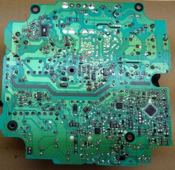
    After replacing these elements and making sure that the power supply of IC1 does not exceed the permissible 17V for it (it has an internal zener diode for this voltage), the main converter started to start but released a voltage at the output significantly exceeding the final charging voltage of the battery. It turned on for a split second with the relay and the fan and everything turned off.

    So I looked at the feedback circuit and the PC3 optocoupler turned out to be damaged. It is soldered under the transformer so the access is best after desoldering the transformer. After replacing, everything started and the charger works properly. Maybe someone will find this description useful.

    Let me just mention that the R28 was "burned" and only after desoldering and measuring with the technical method it showed damage. It was the same with the R31. D16 and D17 diodes can also be measured only after lifting at least one leg from the board.
  • #42 18916341
    NNTFD
    Level 11  
    Cool.
    Congratulates my colleague on your persistence in the fight against this charger. :)
    I gave up, but with this description I will probably come back to check again what hurts her.
    Thanks for the detailed description.
  • #43 18958018
    bigrom
    Level 14  
    I was helped by the replacement of the L6599AD chip
  • ADVERTISEMENT
  • #44 19024770
    ionel calota
    Level 10  
    If R42 is burned, J3 is replaced by L6599.
    D9, R31, R32, D17, D16, R59 are verified
  • #45 19351702
    misqu007
    Level 9  
    Hello
    I have the same smd elements burned as my colleagues above. Could any of my dear colleagues give me the values of the elements:
    D9 (diode marking 94 K)
    D16 (I know from 15 V but how much W?)
    I have the same symptoms as others, i.e. after connecting to the network, the green LED is on and after inserting the battery - 5 is charging and turns off
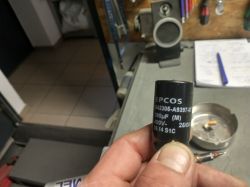
    For tax purposes, I would like to inform you that after connecting to the network, you can hear a strange noise in the vicinity of this large electrolytic condenser - is it dry?
    Thank you in advance for your help
  • #46 19351893
    ionel calota
    Level 10  
    D9= schotky -1A/40v
    ZD16= zener 5v1- 0,5w
  • #47 19353524
    misqu007
    Level 9  
    Thank you for the fast reponse !

    Added after 2 [minutes]:

    ionel calota wrote:
    D9 = schotky -1A / 40v
    ZD16 = 5v1 zener- 0.5w

    Was it supposed to be 15V and not 5V1?
  • #49 19362168
    krakarak
    Level 42  
    "Probably defective capacitor" ... Then you don't have any capacitance or ESR meter? From what did you draw such a conclusion? Is it swollen, or did you think the yellow glue next to it was a leak?
    If you just assumed it and did not measure it, it is an error. Although you can buy an electrolytic capacitor of similar capacity (voltage 400-450V) and dimensions (so that it will fit), but this one can be measured as well - the meter for diode measurement, you put the plus leads to plus minus to minus, look at its indications and wait until it recharges, then you swap the meter leads and watch it discharge and recharge for a long time. Do this several times and compare it with the charging and reloading time of a new capacitor of similar capacity, e.g. 470uF (voltage irrelevant).
    Primitive method, but when there were no capacity meters, I used it successfully. A capacitor that has lost capacity will charge quickly and will recharge just as quickly if the wires are reversed.
  • #50 19362314
    misqu007
    Level 9  
    You are right that I approach it wrong, but I am already running out of ideas, and I know one hundred percent that there is a logical solution to this problem.
    I checked the capacitor by your method. Both processes, i.e. charging, then discharging and recharging, are temporally similar (from 5s to 6s).
    I found a 470 capacitor on some IC and its "processes" were 2s longer. I have not found anything with a closer capacity.
    Are you able to draw any conclusions from this old method of validating a capacitor?
  • #51 19362323
    krakarak
    Level 42  
    I assume the capacitor is functional.
  • #52 19364736
    Strumien swiadomosci swia
    Level 43  
    It is enough to measure the voltage on it.
  • #53 19593687
    msztula
    Level 15  
    Can someone help me? I have lost these elements, some I do not know what to be, please help
    Hilti C4/36-350 Charger Issue: Green LED Flashing Every 2s, Battery Not Charging
  • #54 19827045
    dwwildom33
    Level 1  
    NNTFD wrote:
    Hello, Do you have a wiring diagram for this charger? I need to read the fuse values.

    I have a similar problem with the Hilti C4 / 36-350 charger.
    I have already repaired a few such chargers and most often IC1 or transistors were damaged.
    I have a case in the workshop that has no damaged transistors, neither IC1 nor IC2 MIP2M2. I checked IC1, there is no short circuit between pin 12 and 10. Moreover, I measured the supply voltage of IC1 during charging and it is 13.7V - ok. I replaced IC1 prophylactically and nothing. 5 seconds after starting charging, the charger turns off. I checked optocouplers and also ok. Any ideas what else could be wrong?
  • #55 19854635
    bioly05011
    Level 10  
    Hello, a few elements of the triac burned me on the back of the board, the bridge three resistors, I also burned the resistor marked R7 and I don't know what value is there, is any of you able to say what is the value on it?
  • #56 20013645
    DRAZEK87
    Level 15  
    Welcome

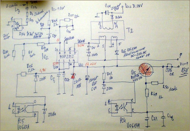
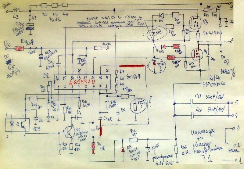
    I received a damaged charger of the above-mentioned model in a dead condition, the cause of the damage is unknown. After the initial inspection and measurements, a lot of small components were damaged, and you also describe burned tracks. Since the diagram of the charger is still unknown today, and so many elements have been damaged, some of which cannot be identified due to their "evaporation", I decided to do my homework and draw a diagram, and thus correct many mistakes made by the above-mentioned people ... and make repairs easier in the future.

    The diagram I present concerns only the primary part of the power supply and only the section that I need to repair; I will add and divide it into two blocks, of which I present the final one today.

    The UC1 system is L6599AD Vcc power supply from approx. 9V to max 16V pin 12 and here for correction it is driven by Q5 transistor, and (not Q3) BCP54, there is a R42 resistor between them, and (not R51 because R51 has 2k? and supplies another part block of the power supply) with a value of 10?.

    The Q3 and Q4 transistors are SPP12NM50ND and are the keys of the main converter.

    The Q6 transistor is the BC817-40 NPN transistor in the SOT-23 package and the 6Ct marking, and (not 6C1 as mentioned by user @ rsv6).

    The D9 diode is SS05D in the SOD-123 housing and marked B4, and (no 94 as user @ misqu007 mentions) Schottky diode 40V / 0.5A here I used SS14.

    The D16 and D17 diodes in the SOD-328 housing and marked with E are 35V / 0.1mA switching diodes, they can be replaced with the popular IN4148 diode; it is worth noting that the manufacturer used this type of element in the catalog note of the system.

    All the values given in the drawing are measured and checked; correct unless it is annotated to an element. I marked the damaged elements and places of burned paths in red.

    Hilti C4/36-350 Charger Issue: Green LED Flashing Every 2s, Battery Not Charging
    Questions:
    1. What is the voltage of the Zener diode ZD9 and ZD10?
    2. What is this PTC1 element, is it a capacitor?
    3. Is the substitution of the ZD16 diode as 5.1V confirmed; for me is this diode working?

    If there is any error, sorry, and soon the second part of the IC2 diagram, i.e. MIP2M20, the documentation of the system in the appendix.
    MIP2M20MS-...asonic.pdf Download (680.28 kB)
    :arrow: I have corrected TONI_2003
  • #57 20031745
    DRAZEK87
    Level 15  
    welcome back
    First, thanks to TONI_2003 for the corrections; it looks much better ...
    Next, I promised the second part of the diagram with the MIP2M2 chip (the only version of the MIP2 chip that does not have pin 6 used). See photo
    Hilti C4/36-350 Charger Issue: Green LED Flashing Every 2s, Battery Not Charging
    The IC2 system is the main converter that gives power to all electronics, and exactly 13V pin 4. In my case, the ZD17 diode was damaged (I initially put 15V because I had it, i.e. it can be seen in the diagram, but in the final stages I changed it to 13V and it works correctly) and the transistor Q5 which is BCP54. Its short circuit caused the charger to be in a dead condition, even though the MIP2 chip was not damaged, it was cool enough because it is difficult to access and relatively expensive.

    It is worth adding that at this stage the charger does not show any sign of life; but the lack of IC1, keys and despite the "blown up" general cargo, if we have IC2, we should have 13V on the C39 capacitor and, which is very important for a quick diagnosis, the LED lights up in green. Behind the Q5 transistor we will not get voltage (despite the working electronics) if the battery is not inserted. The converter on the IC1 chip will start only if the battery is placed and it gives more than 36V. In my case, the transistor Q3 did not completely short-circuit like Q4 because it measured correctly, but it got such a "shot" that after replacing only Q4, the heat sink in the form of a sheet quickly heated up to a very high temperature, and thus it was impossible to touch it after a few minutes of charging and you need to mark the maximum start of the fan at the start, but after the repair, this problem disappeared. Only the replacement of both transistors (in my case without an insulated housing, which also had to be used with additional insulation) brought the correct results.

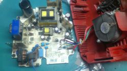
    Finally, I will add that there are two versions of this type of power supply because please pay attention to the photo of the user @ updown5678, and the photos of other power supplies and what I present to you, in my case there is no D14 and R23, R3 or C23 diodes directed to the L3 coil, but it is an additional block of electronics (general cargo) that I did not draw. As for the ZD09 and 10 diodes, I used 15V there and they work properly. Now repairing this model should not be a problem for you at the end of a few photos. The charger is fixed and is doing well.

    Hilti C4/36-350 Charger Issue: Green LED Flashing Every 2s, Battery Not Charging Hilti C4/36-350 Charger Issue: Green LED Flashing Every 2s, Battery Not Charging Hilti C4/36-350 Charger Issue: Green LED Flashing Every 2s, Battery Not Charging Hilti C4/36-350 Charger Issue: Green LED Flashing Every 2s, Battery Not Charging Hilti C4/36-350 Charger Issue: Green LED Flashing Every 2s, Battery Not Charging Hilti C4/36-350 Charger Issue: Green LED Flashing Every 2s, Battery Not Charging
  • #58 20196280
    msztula
    Level 15  
    Another question is what value of the capacitor C8
  • #59 20243186
    anmezdysk
    Level 6  
    Hello
    I have 13V on pin 4 of IC2, but there is no voltage on pin 12 of IC1 - what could be the reason for this?
  • #60 20245938
    msztula
    Level 15  
    I replaced almost everything in this system, diodes, resistors, even mofsets, I was sure that everything would be fine, but after connecting it was a big bummm, I forgot to put the light bulb on the power supply in a row, the board burned down so much that I no longer have the strength to repair again

Topic summary

The discussion revolves around issues with the Hilti C4/36-350 charger, specifically a problem where the green LED flashes every 2 seconds and the battery does not charge. Users suggest that the flashing LED indicates a standby mode or a power supply issue. Several participants share their experiences with similar problems, often related to damaged components such as the L6599AD chip, MIP2M2 IC, and various zener diodes. Common solutions include replacing these components, checking for shorts, and ensuring proper voltage levels across the circuit. Users also discuss the importance of verifying the integrity of other components like resistors and transistors, and some provide detailed measurements and schematics to aid in troubleshooting. The conversation highlights the complexity of diagnosing and repairing the charger, with many users sharing insights on specific parts and their values.
Summary generated by the language model.
ADVERTISEMENT