logo elektroda
logo elektroda
X
logo elektroda

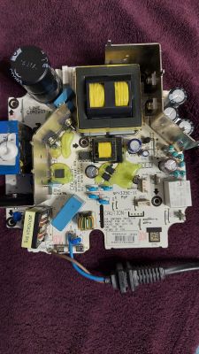
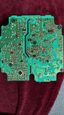
Hilti C4/36-350 Charger Issue: Green LED Flashing Every 2s, Battery Not Charging

rsv6 107361 224
ADVERTISEMENT
Treść została przetłumaczona polish » english Zobacz oryginalną wersję tematu
  • #61 20253201
    DRAZEK87
    Level 15  
    anmezdysk wrote:
    Hello
    I have 13V on pin 4 of IC2, but there is no voltage on pin 12 of IC1 - what could be the reason for this?


    After all, you have an answer in the diagram Q5 transistor, I also flew; and in general, start by checking whether you have a short circuit on the 12th pin, it is best to desolder IC1 on the spot; and if you replace q5 and it does not play, you have something damaged from the base side of this transistor ...
  • ADVERTISEMENT
  • #62 20256662
    anmezdysk
    Level 6  
    Hello
    The voltage is present on the Q5 collector all the time, while the voltage on the Q5 emitter appears only for 10s after it is turned on and it disappears. At this time, the relay and the fan turn on. I think that the problem is in the base-voltage control on the base also disappears after these 10s. The PC4 optocoupler has been checked, it's ok, but what controls it?
  • #63 20257616
    DRAZEK87
    Level 15  
    and you desoldered IC1? or for a quick diagnosis, desolder the resistor R42 10R ... and write what next
  • #64 20264533
    anmezdysk
    Level 6  
    Unfortunately, neither lifting the resistor nor replacing IC1 brought anything new and it is still as it was before. It is appropriate to pursue the topic as it is a more honorable than business matter. Maybe some other suggestions will move things forward?
  • #65 20264863
    rsv6
    Level 13  
    It seems to me that the top256 is now only offal. That's why it doesn't work.
  • #66 20265193
    anmezdysk
    Level 6  
    TOP256 in this charger is not present
  • #67 20266538
    krakarak
    Level 42  
    My mate anmezdisk, maybe attach a photo, because in fact this charger is available in different hardware versions. It will be easier for help.
  • ADVERTISEMENT
  • #68 20270000
    anmezdysk
    Level 6  
    My charger is identical to the first photo in this thread
  • #69 20284669
    11strelec1
    Level 5  
    Hilti C4/36-350 Charger Issue: Green LED Flashing Every 2s, Battery Not Charging Hello everyone.
    I need help with this repair.
    The ice is constantly flashing.
    All diodes, transistors, optocells, capacitors, resistors, IC 1 and IC2 are fine.
    What I found is that at the output of IC 2, after exceeding the voltage of 12 volts, the voltage drops and then it repeats itself. It seems to me as if the circuit is not stabilized.
    Measurement of zeners after soldering.
    ZD 17 20V
    ZD 14 11V
    ZD 15 11V
    ZD 11 15V Hilti C4/36-350 Charger Issue: Green LED Flashing Every 2s, Battery Not Charging

    Added after 1 [hour] 29 [minutes]:

    bioly05011 wrote:
    Hello, a few elements of the triac burned me on the back of the board, the bridge three resistors, I also burned the resistor marked R7 and I don't know what value is there, is any of you able to say what is the value on it?


    R7= 390R
  • #70 20291643
    Matrix8283
    Level 2  
    Hi all, firstly special thanks to DRAZEK87 for the schematics, couldn't have figured my issue out without these schematics, so greatly appreciate the work this person put in. I have one of these chargers for less than a year, probably used 5-10 times when it stopped working. I tested a few components and found ZD17 was shorted. I replaced this ZD17 with a new zener 15v and that blew straight away after powering up. I ordered new MIP2M2 IC and L6599AD chips. After they arrived I replaced both chips and found it was still not working. After further tests I found ZD16 blown. I replaced ZD16 with 15v Zener and it repeatedly got destroyed 3 times. After further inspection I realized ZD16 value is actually 5V1, I then replaced both MIP2M2 IC and L6599AD and ZD16 with correct 5V1 and the charger is now working perfectly. I hope this may help someone fix their charger.
  • #71 20297729
    11strelec1
    Level 5  
    After switching on, the voltage rises to 323V and after a few seconds drops to 307V.
    Measured on MIP2M2 pin 5.
    Is it possible that the system falls due to low supply voltage?
    DRZEK87 writes that pin 5=327V
  • #72 20299758
    DRAZEK87
    Level 15  
    11strelec1 wrote:
    When turned on, the voltage rises to 323V and after a few seconds drops to 307V.
    Measured on pin 5 of MIP2M2.
    Is it possible that the chip will fail due to low supply voltage?
    DRZEK87 writes that pin 5=327V


    of course, there is 327V on pin 5, because see in the first diagram you have a "network" input on the way, the L2 coil and it falls on the 390uF network capacitor for 400V, so here we have some spare then through 3x1R resistors and 9 transformers on the tap, but it goes on to MIP2M2 przz second traffic; the fact that you have 307 there is no tragedy, because maybe you have a lower voltage in the network than others ... it is important that you get 13V on pin 4 of this system, it will give you the effect of a green diode, then you check Q5 and go to the IC1 system, at the end, you assemble the keys when you are sure that IC1 works ... because the keys should be soldered first because they usually get damaged ...
  • ADVERTISEMENT
  • #73 20301996
    11strelec1
    Level 5  
    ..on pin 4 the voltage oscillates from 8.5V to 14.5V. The voltage is not stable. That's why the diode flashes green. Transistor Q5 is fine.
  • #74 20307384
    DRAZEK87
    Level 15  
    11strelec1 wrote:
    .. on pin 4 the voltage oscillates from 8.5V to 14.5V. The voltage is not stable. Therefore, the LED flashes green. The Q5 transistor is fine.


    if you remove J13 (the 0R resistor is right next to Q5) there should be a stable 13V; if it doesn't have IC2 it's working incorrectly,,, you need to check it
  • ADVERTISEMENT
  • #75 20310227
    11strelec1
    Level 5  
    ...after removing J13, nothing changes. The green LED keeps flashing.
    IC1 is replaced with a new piece.

    Added after 21 [minutes]:

    IC2 is replaced with a new piece.
  • #76 20311722
    anmezdysk
    Level 6  
    Hello
    of course, there is 327V on pin 5, because see in the first diagram you have a "network" input on the way, the L2 coil and it falls on the 390uF network capacitor for 400V, so here we have some spare then through 3x1R resistors and 9 transformers on the tap, but it goes on to MIP2M2 przz second traffic; the fact that you have 307 there is no tragedy, because maybe you have a lower voltage in the network than others ... it is important that you get 13V on pin 4 of this system, it will give you the effect of a green diode, then you check Q5 and go to the IC1 system, at the end, you assemble the keys when you are sure that IC1 works ... because the keys should be soldered first because they usually get damaged ...
    My question to clarify what are these keys?
  • #77 20315778
    DRAZEK87
    Level 15  
    Q3 and Q4

    SPP12NM50FP transistor N-MOSFET 550V / 12A / 0.35R; TO220
    STP12NM50FP N-FET 500V/12A 35W To220

    it is important that it is in the FP version, i.e. insulated, I couldn't buy one, I used a regular one, but I had to give insulation in the form of a thermally conductive mica spacer ...
  • #78 20316962
    11strelec1
    Level 5  
    Unfortunately, I don't have much experience in this part. It can be said that I am only learning in the field of electronics.
    What keys?
    I have voltage on pin 4, but it is not stable, as a result of which the LED blinks. I know the power supply path that you describe, and it seems that the components are fine.
  • #79 20353235
    Matrix8283
    Level 2  
    Hi everyone, my charger stopped working again. Now when I plug it in I get a steady green LED, when I insert the battery the relay clicks and then the LED goes out, when I remove the battery the LED comes on again. Any help would be much appreciated. Thanks
  • #80 20355177
    DRAZEK87
    Level 15  
    Matrix8283 wrote:
    Hello everyone, my charger has stopped working again. Now when I plug it in it has a steady green led on, when I put the battery in the relay clicks then the led goes out, when I remove the battery the led comes on again. Any help would be greatly appreciated. Thanks


    Or maybe the battery is damaged and shorts out when you put it in the charger?
  • #81 20393651
    griszka77
    Level 12  
    Hello gentlemen, a replacement for the V0615-9 optocoupler
  • #82 20407961
    DRAZEK87
    Level 15  
    I have never had the opportunity to check if the VO615a optocoupler is interchangeable with the PC817. Comparing the documentation, the pinouts are theoretically the same; insulation voltage 5000Vrms too; PC817 is probably weaker because the output voltage is up to 35V, and the original is 70V and has a slightly higher forward voltage, typical Vf = 1.43 V, while PC817 Vf = 1.2V.

    Another thing is that most of the power supplies I've seen are usually built on PC817, and that some invention was used here, which, as it turns out, is also easily available on a well-known auction site or under the number: VO615A-2X016 in a store I know and like: https:// www.tme.eu/pl/details/vo615a-2x016/optocouplers-analog-output/vishay/

    Ps. In my time, a lot of power supplies from different manufacturers were repaired, but as far as I had repairs, I did not have to replace the optocoupler despite the fact that the power supply was burnt to a large extent. Today, I do not always calculate the repair of a power supply or charger because sometimes you will spend more time on it than it is worth. The one mentioned above is expensive, so it is worth considering substituting PC817 for posterity. Regards
  • #83 20418109
    mrtungckd
    Level 1  
    teskot wrote:
    Hello,
    I have been struggling with the repair of such a charger for several days and it finally worked yesterday.

    Symptom: steady green light, not charging. After installing the battery, the relay and the fan were turned on for 5 seconds, and then everything returned to the starting point.

    After preliminary measurements, damaged:
    IC1
    Q6
    R28
    J3
    D9
    ZD16
    R31
    R51
    Q3
    Q4
    D16
    D17
    F3

    After replacing these elements and making sure that the power supply of IC1 does not exceed the permissible 17V for it (it has an internal zener diode for this voltage), the main converter started to start but released a voltage at the output significantly exceeding the final charging voltage of the battery. It turned on for a split second with the relay and the fan and everything turned off.

    So I looked at the feedback circuit and the PC3 optocoupler turned out to be damaged. It is soldered under the transformer so the access is best after desoldering the transformer. After replacing, everything started and the charger works properly. Maybe someone will find this description useful.

    Let me just mention that the R28 was "burned" and only after desoldering and measuring with the technical method it showed damage. It was the same with the R31. D16 and D17 diodes can also be measured only after lifting at least one leg from the board.

    I have the same problems. But nothing burned. I replaced PC3 following you. Charger still cuts off after 5 sec, nothing changed.
  • #84 20418803
    krakarak
    Level 42  
    I put PC817 into Hilti chargers and they worked as they should.
  • #85 20472469
    DRAZEK87
    Level 15  
    i.e. I helped with this PC817 .... listen, there is no charger that cannot be repaired .... it's either lack of skills / systems / time or willingness, unless it's a burnt hole through and it goes to patch .... unless multi-layer board is then a problem ....
  • #86 20472479
    griszka77
    Level 12  
    Hello, I replaced these systems even with the original ones as they should be, nothing gave the same effect 5 seconds and turns off
  • #87 20486756
    barbaroskuyucu
    Level 2  
    C7.....?
    not found
    Can you measure and write the value, please?
  • #88 20487064
    piterkkpiotrk
    Level 5  
    Hello.
    Thank you to my friend @DRAZEK87 for making the diagram. Diagnostics were not difficult, but there was a problem with the availability of the L6599D system.
    Did any of your colleagues order more parts to repair this charger and could share?

    Thank you for your help.
  • #89 20487078
    griszka77
    Level 12  
    After all, you have allegro
  • #90 20487226
    piterkkpiotrk
    Level 5  
    I meant versions with AD at the end and I was thinking about D and so I wrote it wrongly.
    L6599AD I didn't find it to get it quickly.
    In the note I saw that there are other parameters for the softstarter,
    Are these chips interchangeable?

Topic summary

The discussion revolves around issues with the Hilti C4/36-350 charger, specifically a problem where the green LED flashes every 2 seconds and the battery does not charge. Users suggest that the flashing LED indicates a standby mode or a power supply issue. Several participants share their experiences with similar problems, often related to damaged components such as the L6599AD chip, MIP2M2 IC, and various zener diodes. Common solutions include replacing these components, checking for shorts, and ensuring proper voltage levels across the circuit. Users also discuss the importance of verifying the integrity of other components like resistors and transistors, and some provide detailed measurements and schematics to aid in troubleshooting. The conversation highlights the complexity of diagnosing and repairing the charger, with many users sharing insights on specific parts and their values.
Summary generated by the language model.
ADVERTISEMENT