logo elektroda
logo elektroda
X
logo elektroda

Hilti C4/36-350 Charger Issue: Green LED Flashing Every 2s, Battery Not Charging

rsv6 106260 223
ADVERTISEMENT
Treść została przetłumaczona polish » english Zobacz oryginalną wersję tematu
  • #181 21228298
    jan262
    Level 5  
    Hello, does anyone have the value of the Z2 varistor? It got a ricochet when the triac failed and I can't read its value.
  • ADVERTISEMENT
  • #182 21228443
    TONI_2003
    Moderator
    Look in this topic on its several pages: Link (1~7) or there: Link . You should have given a photo along with where this component is!
  • #183 21228508
    jan262
    Level 5  
    >>21228443 >>21228443 Fragment of an electronic circuit with visible capacitor and connectors. .
    It is located next to the rectifier bridge. A search of the topic did not yield fruitful results.
  • #184 21228645
    TONI_2003
    Moderator
    Forgive me, but in my mind right from the first photo in that topic you can see that probably the Z5 is the same as the Z2 :)
    Close-up of electronic components with pink arrows pointing to specific elements.
  • #185 21245559
    idaffi
    Level 8  
    Hi!
    I got my hands on the same charger, I'm sure at least the MIP2M2 is broken, I ordered from Ali but I have a jumper on legs 7 and 8 on every one I ordered, will you guys provide a link where you ordered from and it worked? :)
    Greetings
  • ADVERTISEMENT
  • #187 21249312
    idaffi
    Level 8  
    >>21248983 .

    I managed to get a working charger a few days ago, there on the diode test on the 7th and 8th pin the result was around 600 (I'm away so have no way to check)
  • #188 21254998
    idaffi
    Level 8  
    I found some description for this MIP, there should not be a short circuit between them, so the Chinese sent instead of MIP2M2 some H2 :D Diagrams of the Mip2M2 power integrated circuit. .
  • ADVERTISEMENT
  • #190 21256790
    idaffi
    Level 8  
    >>21256754 .
    It was some Thai or Vietnamese site, I got to probably the 5th page on Google :D
  • #191 21256916
    keklikozcan
    Level 4  
    Hi I have a problem. When I plug the battery, charger starts, fan works and after 10 seconds charger stops. Did anyone solve this problem? I replaced L6599AD IC and MIP2M2 IC but same. Relay, triac, mosfets, all zener diodes good. Battery is good. Anyone can help me?
  • #192 21260921
    DRAZEK87
    Level 15  
    The MIP2M2 circuit is slightly different from the given circuits: MIP2H2 and MIP2F2 in spite of the same external appearance; it must not be interchanged because pin 7 in the MIP2M2 is the "SOURCE" ground and pin 8 is the "LS" signal and there must not be a short between these pins, as I have already written! In the MIP2H2 and MIP2F2 there can be a short circuit because pins 7 and 8 are ground, but I haven't measured the new circuit because I don't have one and I haven't encountered one yet.

    There was a question about the next components and they are varistors of size 07 probably this is the spacing of the legs and they are for voltages:
    Z2 = K275
    Z5 = K385
    Z4 = K420
  • #193 21260993
    kazikszach
    Level 38  
    DRAZEK87 wrote:
    There was a question about the next items and they are varistors of size 07 probably this is the leg spacing,
    .
    This is not the leg spacing but the diameter of the varistor.
  • #194 21261906
    DRAZEK87
    Level 15  
    Rather the diameter, and with it the leg spacing; all 3 are the same diameter, but you can see that the higher the voltage, the thicker it is. I rarely replace them, but I have made myself a large set of different values, a few at a time, to always have in reserve, even for substitution when an emergency occurs....
  • #195 21297285
    florian_1034
    Level 2  
    Hello everyone,
    I join the discussion with 3 defective chargers.
    One has serious water damage/corrosion and no attempt to repair will be made. The others will be named charger 1 and 2.

    Charger one was doing nothing. At close inspection, I could find IC2 shorted between drain and ground, R30 R33 (1Ohm resistor) burned. Q3 and Q4 were fine.
    I switched the ic2 circuit from the water damaged one to this, and replaced the burned components.

    The charger switched from no working case, to green light, insert battery, start fan and relay for 5 seconds then stops with green light on.
    I checked the gates of the MOSFET's and was apparently shorted between the gate and source. The short was coming from the IC1. I can not explain why. But the chip seems to start working when measured by the DMM and close the contact between mosfet gate output and drain pin (measured before R23 or R32). Tested on a new IC and found the same behavior. It was enough to touch with my fingers the chip and the short was gone. Be careful when measuring these chips. They can give false short circuit readings between HVG-OUT and LVG-GND.

    Anyway, I replaced the chip and nothing changed.
    Later I found that J3 was burned. Was the last component to think that can be burned and checked it only after reading this topic. Replaced, same results.

    At this moment, I have no idea what can be the problem. I can only list my measurements and what I tried,
    I checked and de-soldered where was the case all the components around IC1.

    Line and Dis are ok.
    The uC is commanding the IC1 to start.

    When starting, the gate of Q3 gets a short trail of impulses and then everything stops. RFMIN goes to zero, VCC remains at 13V.
    I supplied IC1 directly with 13V external, wired a 1.5V battery between the GND and LINE pin to enable the conditions of LINE>1.2V and DIS <1.8V.
    When doing this, the chip comes alive and I have the right signals on the mosfet's gates (25Khz, 50% dtc pwm).
    Then I tried to supply the main capacitor C3 with an increasing voltage up to 16 volts. IC1 works till I reach the voltage of apx 10 volts (sometimes 3 volts).
    I can put a load on the secondary (3w light bulb) and it will work.
    The chip suddenly stops if I increase the primary voltage (and by stop I mean no gates pwm, RFmin voltage collapses, need to recycle vcc to restart)
    De-soldering the transformer pin and hooking up a light bulb of 25W between the Q4 drain and, the chip remains on even if supplied with 16 volts.
    Moving the light bulb wire to GND (so that the Q3 will switch the light) and the chip stops again when approaching 10 volts.

    I tried with Dis grounded, Isen disconnected. Measuring all the diodes with the dmm, all capacitors de-soldered and checked. When at 10 volts, the voltage across C19 and C20 oscillates at 300 volts if no load is applied to secondary. With load, at 40 volts.
    I changed the mosfet with the donor one.
    De-soldered the optocoupler.
    Looks like the chip is latched in a protection state. Only two are latched. OCP and DIS. I tied both to ground and still latches so... ???
    I have no ideas.
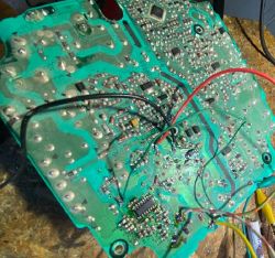
    Damaged electronic circuit board with visible wires and solder traces.

    Charger 2. ..green light, insert battery, start fan and relay for 5 seconds then stops with green light on.
    Changed the IC1, worked fine for a day, charging with 8 amps. Next day, was not.
    Apparently, IC1 is burned again. (400 ohms between vcc and gnd and is getting hot). Forgot to check the Vin voltage...

    Any ideas regarding the first charger?
  • #196 21309330
    adriancopou
    Level 1  
    Hello everyone,

    I have a charger like this which initially didn't even have the green LED on when powered on. I saw that the lack of 13V voltage at pin 4 of MIP2M2 means the integrated circuit is defective so I ordered a new one and replaced it. Now I have 13V on pin 4, and the green LED is on, but in the emitter of Q5 I don't have 13V. I saw that on the optocoupler PC4 there is no voltage on the diode (input pins 1,2), so it is normal that Q5 does not have 13V in the emitter. I couldn't find a schematic to see who controls the diode in PC4, so I ask for your help. If I'm not mistaken I saw that the microcontroller would command PC4, but without the 13V I can't figure out what powers the microcontroller? If I understand correctly, without the 13V nothing works.

    On MIP2M2 I have:
    - pin 5 : 323V
    - pin 4 : 13.1V
    - pin 1 : 5.95V
  • #197 21313155
    florian_1034
    Level 2  
    >>21309330
    Hi,
    "without the 13V nothing works" is a false statement.
    T2 has two secondaries. One is providing the 13V for the high voltage electronics and another one of 8.4V that is powering the low voltage side.
    If you search closely on this forum, there is a handmade schematic that presents PC4 being commanded by pin7 of the micro-controller.

    PC4 will only be activated if the battery is inserted and is ready to charge.

    There are two power supplies.
    One is a standby/logic power supply driven by MIP2M2
    Another is a high power 8A ~25V power supply driven by the IC L6599AD.

    L6599AD VCC is commanded by the PC4, when PC4 is on, L6599AD starts and hopefully the entire high power supply starts.

    If high power supply fails to start (micro controller does not detect any current on the low side), the micro-controller will switch off PC4 in about ~5 seconds and remain in that state with green led on.

    L6599AD will theoretically not start according to the datasheet if:
    1. the LINE pin voltage is too low
    2. the DIS voltage is too high
    3. the second over current limit was exceeded
    4. the STDBY voltage trigger the burst mode
    5. Vcc is below the starting threshold voltage.
    Check the datasheet for the exact limits.

    In my case, even with all this condition fulfilled, the chip refuses to start and RFMin voltage drops to zero.
    I do suspect that the ic is also checking if the tank oscillator is oscillating at the right frequency. but is not specified in the datasheet. (it starts for a brief moment then dies).
    Also, a tank circuit out of tuning may induce some spikes into the chip triggering one of the latched protections. (Bad capacitor or diode...who knows)

    Good luck!
  • #198 21365298
    RADOSŁAW
    Level 16  
    The charger would switch off after about 5 s.
    In my case the damaged L6599AD and Q6 inserted BC847B
    The supply voltage of L6599AD at me is 14V.
    I confirm for PC3 V0615A-9 you can insert PC817 at me it works.
  • #199 21368360
    idaffi
    Level 8  
    Hello Gentlemen,
    As far as I can see at my place, there is no voltage coming on MIP2M2, hence no response to the connection, capacitor C3 charges normally to about 325-330V, while 327V is not coming on MIP anymore, where to look next?

    Added after 1 [hour] 6 [minutes]: .

    >>21368360 good, I traced the paths and it's a line of resistors R24, R30 and R33, at first I thought it was the laminate's fault that my probes weren't catching the measurement, tomorrow I'll buy new ones and let you know if it caught on
  • ADVERTISEMENT
  • #200 21370006
    idaffi
    Level 8  
    >>21368360 the voltage appeared on the MIP, the green LED comes on and after a while goes off, so there is some progress

    edit: on the 4th pin of the MIP the voltage jumps between 8.5V and 11 with a hook, at 11 the diode lights up for a while, on the 5th pin there is a stable 327V, MIP to replace or could it be something else?
  • #201 21375166
    DRAZEK87
    Level 15  
    idaffi wrote:
    >>21368360 voltage appeared on the MIP, the green LED comes on and after a while goes off, so there is some progress

    edit: on the 4th pin of the MIP the voltage jumps between 8.5V and 11 with a hook, at 11 the diode lights up for a moment, on the 5th pin goes stable 327V, MIP to replace or it could be something else?


    unsolder the MIP and compare with the notes what I put in this topic under 20873559 if everything is ok solder it and look further because rather the circuit should be working; probably you have somewhere a short circuit on the main inverter so it comes to reset; first check the circuit! or replace it, although this is unnecessary, if you can't check and be sure about the circuit, further repair is pointless...
  • #202 21408631
    idaffi
    Level 8  
    >>21375166 .
    MIP working, however the voltages after soldering apart:
    pin1: ~1-2 mV
    pin2: -5 mV(!)
    pin3: ~1-2 mV
    pin4: -0.22 V(!)
    pin5: 326 V
    pin8: 1.01 V
    I misspelled with this reset, the diode simply turns on when these ~11 V are reached, but goes off after a while when the voltage drops.
  • #203 21411923
    HackoBoy
    Level 11  
    Cześć - nie chciałem otwierać nowego tematu.
    W moim przypadku po włączeniu ładowarki następuje aktywacja przekaźnika - po rozpoczęciu ładowania i aktywacji przekaźnika proces zatrzymuje się po 5 sekundach, a ładowanie jest wznawiane po 2 minutach. Nie ma znaczenia, czy napięcie akumulatora wynosi 18 czy 21 woltów.
    Po uruchomieniu BMS-a - podłączając zacisk do + akumulatora (oznaczonego D) mam napięcie samego akumulatora. Ale gdy zaczyna się ładowanie - napięcie spada do 19 woltów.
  • #204 21420371
    HackoBoy
    Level 11  
    Po wymianie jednego z ogniw Samsung 21700 40t poddałem je zrównoważonemu ładowaniu i rozładowywaniu. ALE ładowarka nadal robi to samo.
    Po zbliżeniu się (cewka z diodą LED nawiniętą na ferryt) dioda LED zaświeciła się na jednym transformatorze (mikro), lecz nie zaświeciła się na dużym transformatorze. Widziałem, że 12n50dm2 ma jedną nogę oderwaną (była ukryta)
    Jakim innym mocnym tranzystorem MOSFET N-FET mogę go zastąpić, nie psując przy tym samej ładowarki?
  • #205 21435675
    akalarus123
    Level 2  
    Hello.
    Does anyone know the parameters of the trafo marked T2 in the diagram - manufacturer's designation Z3M8A (the internet doesn't spit out anything by these designations). Any suggestion what to replace it with?
    Mine has biodegraded when exposed to water.
  • #206 21437863
    HackoBoy
    Level 11  
    Hello. Do you have c4/36 350 circuit. I measure Voltage - and see this. MIP2M2 - pin4 have 15V, Q5 Collector 15V, Optocoupler PC4 pin4 (C) 13.5V, but pin3 (E) have 7.5V -> this voltage on Base Q5 = have Emitter same voltage on pin.12 L6599 (turn OFF). Voltage PC4 diode - measure 0.25V. I think this is problem low voltage - not open optocoupler. I need help This Optocoupler - which element controls this optocoupler
  • #207 21477150
    marchakoleg911
    Level 3  
    Hello!
    I have this problem with charging!
    I switch on the charger, everything is ok. I insert a battery with 4 dashes ( -24v), it charges up to 25v and shuts down. I insert a battery with 1-3 dashes, below 24v the charger starts charging and after 5 seconds it switches off completely, the zelina diode stops illuminating. It has to be disconnected from the socket and switched on again, and it switches off in the same way. After 5 sec.
    when I insert from 24v it is ok. what can happen to it, what to pay attention to
  • #208 21477470
    krakarak
    Level 42  
    On sense and spelling... It's impossible to grasp what you mean....
  • #209 21477531
    marchakoleg911
    Level 3  
    If I insert a discharged battery that has 1 line, or 2, or 3 lines of charge, it makes no difference whether it is a 22 V or 36 V series, it charges for 5 seconds. It will go out completely, the green LED will go out. Remove the plug from the socket and switch it on again. And when I insert the battery with 4 dashes, it charges normally.... the charger does not switch off.
  • #210 21480299
    marchakoleg911
    Level 3  
    >>21477470 .
    if i insert a discharged battery that has 1 charging dash, or 2, or 3 charging dash, it makes no difference whether it is a 22 volt or 36 volt series, it charges for 5 seconds. it goes out completely, the green LED goes out. unplug the battery from the socket and plug it in again.
    and when I insert the battery with 4 charging dashes, it charges normally....

Topic summary

The discussion revolves around issues with the Hilti C4/36-350 charger, specifically a problem where the green LED flashes every 2 seconds and the battery does not charge. Users suggest that the flashing LED indicates a standby mode or a power supply issue. Several participants share their experiences with similar problems, often related to damaged components such as the L6599AD chip, MIP2M2 IC, and various zener diodes. Common solutions include replacing these components, checking for shorts, and ensuring proper voltage levels across the circuit. Users also discuss the importance of verifying the integrity of other components like resistors and transistors, and some provide detailed measurements and schematics to aid in troubleshooting. The conversation highlights the complexity of diagnosing and repairing the charger, with many users sharing insights on specific parts and their values.
Summary generated by the language model.
ADVERTISEMENT