logo elektroda
logo elektroda
X
logo elektroda

Hilti C4/36-350 Charger Issue: Green LED Flashing Every 2s, Battery Not Charging

rsv6 106389 223
ADVERTISEMENT
Treść została przetłumaczona polish » english Zobacz oryginalną wersję tematu
  • #1 17267278
    rsv6
    Level 13  
    [Hello
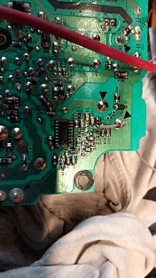
    I have a problem with the Hilti C4 / 36-350 charger, viz. The charger blinks green every 2s and does not charge. No reaction to plugging in the battery.
    Hilti C4/36-350 Charger Issue: Green LED Flashing Every 2s, Battery Not Charging Hilti C4/36-350 Charger Issue: Green LED Flashing Every 2s, Battery Not Charging
  • ADVERTISEMENT
  • #2 17267639
    Sniezynka
    Level 33  
    It flashes and does not charge because it is in standby mode and is charging on a different battery?
  • #3 17267674
    yanes
    Level 32  
    The standby status is the diode that is lit with a constant light, flashing on the connected charger indicates problems with the power supply.
  • #5 17267845
    rsv6
    Level 13  
    Sniezynka wrote:
    I mistook it with another model, here is the instruction; https://www.hilti.pl/medias/sys_master/docume...h6e/9113446055966/PUB_5129959_000_APC_RAW.pdf
    Which LED is blinking? There is nothing in the manual about the power supply problems, only the cell temperature.


    It blinks continuously without a battery or with a battery. The description on the charger shows that it should glow after turning on the power. Does anyone have any schematic? Or someone had a similar problem?

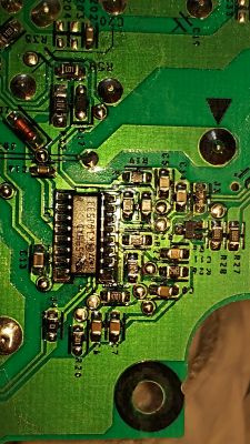
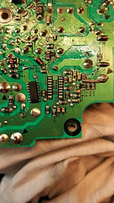
    On the board, I noticed a burned path and jumper J3 with a 0R resistor. Same problem after replacing this item. Before the relay on the capacitors there is 19.5V after turning on the power.

    Hilti C4/36-350 Charger Issue: Green LED Flashing Every 2s, Battery Not Charging Hilti C4/36-350 Charger Issue: Green LED Flashing Every 2s, Battery Not Charging
  • ADVERTISEMENT
  • #6 17267905
    Strumien swiadomosci swia
    Level 43  
    rsv6 wrote:
    Same problem after replacing this item

    But what burns these elements over and over again?
  • ADVERTISEMENT
  • #7 17267916
    rsv6
    Level 13  
    Strumien swiadomosci swia wrote:
    But what burns these elements over and over again
    I wrote a little not clearly. Nothing burns out of the elements now, only the LED is still blinking is not charging.
  • #8 17267945
    szon
    Level 19  
    A friend of mine had probably given me the same one once. I am not sure because it was a long time ago, but the inverter driver was damaged, the 8-pin system in the first photo. Impregnable deal. This is how companies protect themselves, you have to throw out and buy a new one. I emphasize once again that I can be wrong as to whether it was the same charger but rather it was her.
  • #9 17267984
    rsv6
    Level 13  
    szon wrote:
    A friend of mine had probably given me the same one once. I am not sure because it was a long time ago, but the inverter driver was damaged, the 8-pin system in the first photo. Impregnable deal. This is how companies protect themselves, you have to throw out and buy a new one. I emphasize once again that I can be wrong as to whether it was the same charger but rather it was her.

    How did you diagnose it? Which layout in the first photo?
  • Helpful post
    #10 17267985
    Strumien swiadomosci swia
    Level 43  
    I have repaired this type many times, first see why it burned the path and what it powers.
  • #11 17268059
    rsv6
    Level 13  
    Strumien swiadomosci swia wrote:
    I have repaired this type many times, first see why it burned the path and what it powers.


    You're on the right track :)
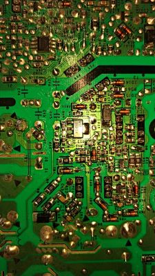
    From what I saw, it powers the 10pin IC1 L6599AD
    10pin is gnd from what I invented in the technical data of the system. I picked up the chip because it has a 45R short circuit between the 10th and 12th pin. The system probably controls the Q3 transistors,
    Q4 12NM50ND
    Hilti C4/36-350 Charger Issue: Green LED Flashing Every 2s, Battery Not Charging Hilti C4/36-350 Charger Issue: Green LED Flashing Every 2s, Battery Not Charging

    I think 45R on the power pins is checked on a raised chip. This is a bit too little resistance. Can you write what else could go in turn?
  • Helpful post
    #13 17268108
    Strumien swiadomosci swia
    Level 43  
    If there is a short circuit in the power supply, do not be surprised, check these power transistors for a short circuit.
  • #14 17268117
    rsv6
    Level 13  
    Sniezynka wrote:


    Thanks, but I have no problem finding the documentation. I am asking for more information about the charger. Possibly from what this system could fall. I checked all diodes and resistors within the system and they are ok. Executive transistors too. Only I am not sure smd short circuit capacitors are not on them. And there is also the Q6 6C1 transistor
  • #15 17268122
    Strumien swiadomosci swia
    Level 43  
    Measure the tension on pins 10-12.
  • #16 17268140
    rsv6
    Level 13  
    Strumien swiadomosci swia wrote:
    If there is a short circuit in the power supply, do not be surprised, check these power transistors for a short circuit.


    There is no short circuit on the soldered ones. The values seem similar on both.
    Relative to the 3-legged plus.
    First transistor:
    minus on 1pin 757mV
    minus on 2pin 423mV
    Second transistor:
    1pin 707mV
    2pin 403mV

    Added after 1 [minutes]:

    Strumien swiadomosci swia wrote:
    Measure the tension on pins 10-12.


    Can I do it without a deal? Because I don't want to put it back in if it's supposed to be short-circuited.

    Added after 3 [minutes]:

    What voltage should there be because I connected directly to the desoldered 5V 10pin- 12+ system and takes 190mA from the workshop power supply
  • #17 17268155
    Sniezynka
    Level 33  
    The circuit probably fell from too high a supply voltage above 17V, see the circuit on page 30 where it is implemented through a stabilizer on the transistor.
    A similar solution may be here.
    It takes so much because it has a short circuit of the internal stabilizer.
  • #18 17268162
    rsv6
    Level 13  
    Sniezynka wrote:
    The circuit probably fell from too high a supply voltage above 17V, see the circuit on page 30 where it is implemented through a stabilizer on the transistor.
    A similar solution may be here.

    Can I run the charger without it? Will I have fireworks. Only if it was a tension do I get thoughts that he has to control it somehow?
  • ADVERTISEMENT
  • #19 17268167
    Sniezynka
    Level 33  
    Unfortunately, without the chip, it will not work properly to replace the chip and to check the power branch, it's like that at the beginning.
  • #20 17268178
    rsv6
    Level 13  
    Sniezynka wrote:
    Unfortunately, without the chip, it will not work properly to replace the chip and to check the power branch, it's like that at the beginning.


    I have already checked it as I wrote above. Nothing to order and check somewhere. Let there be no damage after the second part of the power supply.
  • #21 17268202
    Sniezynka
    Level 33  
    Remember to run on the service power supply by checking the oscillograms on the oscillator transistors.
  • #22 17268250
    rsv6
    Level 13  
    Sniezynka wrote:
    Remember to run on the service power supply by checking the oscillograms on the oscillator transistors.


    What service power supply do you mean?

    If I do not give 230V for the input, the converter and control will not start.
  • #23 17268252
    Sniezynka
    Level 33  
    You supply the system directly from the power supply, and from the 230V network, before soldering the system, you must check the voltage on the leg 12. If you do not check it, the new chip may go away.
  • #24 17268258
    rsv6
    Level 13  
    Sniezynka wrote:
    You supply the system directly from the power supply, and from the 230V network, before soldering the system, you must check the voltage on the leg 12. If you do not check it, the new chip may go away.


    Ok, I should pick up 12pin and give it what voltage? Isn't it better to put a zener diode at maximum voltage?
  • #25 17268269
    Sniezynka
    Level 33  
    You can insert a 9 to 16V zener diode at 16V later, but I suspect that there is a voltage stabilization system there and if it is out of order, it may still damage the system.
    Check if it is realized through Q6 transistor.
  • #26 17268331
    rsv6
    Level 13  
    Hilti C4/36-350 Charger Issue: Green LED Flashing Every 2s, Battery Not Charging
    From what I can see the voltage goes from transistor Q3 BCP54 Through the 10R resistor

    It is controlled by IC2 MIP2M2
    It can be, as "Shon" wrote, that he will be wasted. If so, it is no longer worth fixing it. I will try to run on the new one what the short circuit does and I will know because the second system costs about PLN 50
  • #27 17268343
    Sniezynka
    Level 33  
    For a Chinese, it costs $ 2
  • #28 17268349
    rsv6
    Level 13  
    Sniezynka wrote:
    For a Chinese, it costs $ 2


    I do not trust Chinese elements anymore. I ordered Spw47n60c3 about a year ago, there were some fakes with a punctured inscription that did not open completely.
  • #29 17268367
    Sniezynka
    Level 33  
    I, however, do not follow the price and buy the originals.
    You have to ask for photos of actual elements from nature and compare with those installed in the device.
    Not every Chinese is a crook.
  • #30 17713102
    NNTFD
    Level 11  
    Hello,
    I have a similar problem with the Hilti C4 / 36-350 charger.
    I have already repaired several such chargers and most often IC1 or transistors were damaged.
    I have a case in the workshop that has no damaged transistors, neither IC1 nor IC2 MIP2M2. I checked IC1, there is no short circuit between pin 12 and 10. Moreover, I measured the supply voltage of IC1 during charging and it is 13.7V - ok. I replaced IC1 prophylactically and nothing. 5 seconds after starting charging, the charger turns off. I checked optocouplers and also ok. Any ideas what else could be wrong?

Topic summary

The discussion revolves around issues with the Hilti C4/36-350 charger, specifically a problem where the green LED flashes every 2 seconds and the battery does not charge. Users suggest that the flashing LED indicates a standby mode or a power supply issue. Several participants share their experiences with similar problems, often related to damaged components such as the L6599AD chip, MIP2M2 IC, and various zener diodes. Common solutions include replacing these components, checking for shorts, and ensuring proper voltage levels across the circuit. Users also discuss the importance of verifying the integrity of other components like resistors and transistors, and some provide detailed measurements and schematics to aid in troubleshooting. The conversation highlights the complexity of diagnosing and repairing the charger, with many users sharing insights on specific parts and their values.
Summary generated by the language model.
ADVERTISEMENT