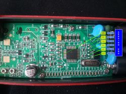
Today I made a mod for my ut210e. Well, the meter is dead. Does not turn on. Once every few clicks, it will be able to turn on, and when it turns on, you can see that the eeprom is changed, because it will be set to volts dc, continuity test and measurement of dc with clamps. But the detection of live wires stopped working, and on the continuity test without any wires connected at all, it beeps all the time and shows 0. The clamp measures nothing either.
What could go wrong? I was uploading via arduino. Of course, I changed two values to my calibration values.
Of course. But I checked the charge and it looks like it's ok. The tip of the soldering iron is grounded, and yet I beat the chip somehow. I mean dm1106. After uploading the batch, the multimeter worked. I checked all the functions and it was ok. Including changes for the better. And after unsoldering the wires from the board, such a knock was done.
I was doing using the program from the eev forum. I used this picture for connection: And I uploaded the program from the attachment. Of course, I just changed it to my calibration data and turned on the record. And it went well. After a few switching on and unsoldering the wires from the pcb of the multimeter, something broke. I read the eeprom again and it's the same. Looks like the DM chip is down. Because there is nothing else there. Only an operational amplifier with a hall sensor and clamps. Edit: Oh, I remembered that I turned it on again after unsoldering the wires from the holes from the board and it was ok, only after unsoldering the reset wire from the capacitor on the left side of the DM system, the meter went crazy. And at the beginning, when I tried to read the eeprom for the first time, the reset did not go without this cable, so it is necessary.
I do not know why play with soldering, since the clip and the programmer are a much safer solution. I also modded my 210E and it works without any problems.
I would ask my colleagues to insert a link with the description of the modification, or to paste the appropriate content. It can be in English or Russian. And we'll have a tutorial article in one. I have not modded mine yet, because there is still something to do, but I want to change the order of functions and turn off the backlight time. Although the range up to 1000A, it can also be useful.
Nothing new. I have already written about it, and even added a description of what the modification gives. I was talking to this guy and from what I found out, the offer is about to disappear or the price will go up. I wanted to send only the batch (because why pay for two multimeter shipments) instead, I proposed to describe the effects here, but he was not interested. In the meantime, I found the previously presented video.
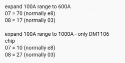
Hello I have made modifications to my meter according to this guide https://mysku.ru/blog/china-stores/48659.html adjusting some parameters for myself. I added an additional DC current measurement submenu up to 6000mA and wanting to correct the 0 calibration, where it was 170mA before, I got 440mA. Then I performed auto-calibration according to http://kazus.ru/forums/showpost.php?p=1019021&postcount=415 As a result, I got nice zeros, but the measurements were overstated by 20-200mA depending on the range. I soldered the eprom again and left the zero calibration on individual ranges (including the new 6000mA) and set the parameters from the addresses 33h 36h 39h 3Ch as it was at the factory. I also did not find an option to increase the range above 100A anywhere, one even wrote that it is impossible due to hardware limitations. Now a meter, more user-friendly.
In my post above is everything. You just better have a good grounded soldering iron, ground yourself, and a suitable so8 clamp. This will reduce the risk of failure.
I bought the UT210E because I was interested in the small range of the measured current (although I admit that I did not believe that it would be reliable in the 2 Amp range).
All versions "can" measure DC current,
According to photos, only D and E. Do you confirm?