Just because you can connect the two wires together doesn't mean you should ... but if you must, the article below will show you how. Of course, the easiest way to connect two conductors is to twist them together. If we know how to do this, the connection can be rugged and mechanically strong, ensuring good electrical contact. However, if you do not know how to make such a connection, check out the video below. It shows several methods used to connect cables together - note how different techniques differ in terms of their mechanical strength.
This method, while it actually allows two wires to be connected, has its drawbacks. Making such connections is very tedious, especially if there should be many of them in a given installation. In addition, the length of the cable used for the connection is large, which translates into how much less wire we have to install, if there are really a lot of such connections, or how much more we have to pay for the wiring of the system (not including labor and personnel costs). that will make these connections). Importantly, such connections cannot be made under voltage under any circumstances, which is sometimes required (and what the connectors are for).
Just because you can connect two wires together doesn't mean you should connect them. They often differ in spacing and the type of conductor (i.e. wire vs line). The thinnest wire in the entire system must be capable of carrying the maximum circuit current. Moreover, the connection between the two wires can increase the series resistance further, especially if the connection is not good or is not matched to the diameter of the wire, for example. This can lead to the connection becoming too hot.
Depending on the voltage and current, there are other standards governing this type of connection. These standards exist for a reason and if you ignore them you do so at your own risk. Sometimes it ends in very unexpected or unpleasant ways. A typical example provided by the author of the article is a rejection of a fire compensation claim due to the use of an inappropriate connector in the power network, even if the connector is in a completely different place in the circuit than the fire occurred. With that in mind, let's take a look at the most popular and used cable connectors for electrical wiring.
Electric Cube
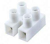
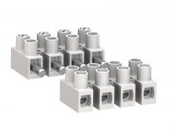
If you want to connect several different circuits with each other, you can use an electrical cube as shown on the left. The subject of cubes is very wide - this is a huge group of connectors that would be difficult to cover in this paragraph, so let's just stop presenting this very popular connector here - most of us had the opportunity to use this type of connection.
"Nuts" for wires
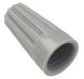
These types of connectors as shown on the right (Molex 0191600039) come in many colors and sizes. They are very popular in electrical installations (not as much in Poland as, for example, in the USA). They are used for connections in the power grid within the premises. The nut consists of a truncated cone made of an insulating material with a thread inside.
The use of such a connection is very simple - take the two isolated ends of the cable, insert them into the cone and just twist. Such a nut allows you to easily connect even grossly mismatched wire diameters, wire with a rope, and also allows you to connect two, three or even four wires at once. Provided that all of the exposed conductors are in the insulated cone, the connection is fully insulated. However, the joint itself is not very strong and a more forceful tug can cause it to disconnect, meaning you should consider whether there may be any mechanical stress in your application. The advantage of this connector is the fact that it can also be unscrewed to allow modifications.
Fork terminals
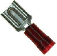
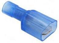
Anyone familiar with automotive wiring will know what fork terminals look like. For those who have not heard about them, on the left there are two photos showing such a connector: at the top - in the female version (Panduit DNF18-250-M) and at the bottom - in the male version (Panduit DNF14-250FIM-M).
Such terminals are crimped on insulated wires with the help of a special device - a crimping tool. Connectors are available in a wide range of insulation colors; very often (as in this case) the color is also an indicator of the recommended thickness of the wire on which the terminal should be crimped.
Usually the "spike" part of this connection is attached to a relay or other device block, and the other part is put on it and sits on the cable, however, as can be seen in the lower left photo, there are also these types of crimp connectors.
Make sure that the entire connection is completely insulated. This is achieved by special connectors that insulate the connection. Fork connectors of this type offer a fairly high resistance to accidental disconnection, even in the event of stronger pulls.
Butt crimp connections
These connectors use the same tools for both crimping and insulation colors as spade lugs, butt connectors (right for examplePhoenix Contact connector 3240061) are often found in the same manufacturer series as the fork terminals.
Such a connector is simply a metal tube (sometimes insulated) into which the stripped end of one wire is placed at one end of the tube, crimped, and repeated for the other wire on the other end.
Ball joints ( bullet connector )
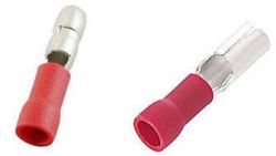
The above-mentioned crimp connection is eternal. However, there is an intersection between a butt joint and a fork joint which is often referred to as a "ball joint" or more commonly in English. bullet connector "Shown on the left is a pair of these Panduit connectors: EBV18-4MB-Q and EBV18-4B-Q.
This type of connection consists of a bullet-shaped metal tube (with a wire clamped on one side), and a similar tube in which the so-called the 'bullet' retracts. An electric wire is also connected to the other tube.
Scotchlok quick coupler
Sometimes we want to use an existing cable for the connection. Of course, you can always cut it and make a three-way connection, for example. There is also a not very elegant and correct practice to remove a small section of insulation on the wire and wrap / solder the tap.
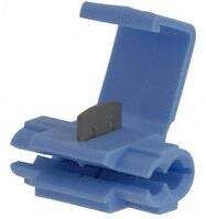
However, a much better solution is available - Scotchlock couplings shown on the right.
This connector has two paths. The main wire (in insulation) is inserted into one of them, and the tap is inserted into the other. The entire connector is closed on both wires, which may require the use of pliers, especially with larger wire cross-sections or thicker insulation. When closing the connector, a special blade is pressed into the insulation, and after passing through it, it touches the inner conductor, short-circuiting both wires located in the element. This type of technology (contact cutting of insulation) is called IDT.
IDT butt connectors
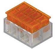
Now that we've introduced one IDT connector, we can see a few more of this type. The photo on the left shows an exemplary IDT butt joint (Keystone 8377). There are many series of these types of connectors, such as the Keystone i-Clamp shown and the Coolsplice series from TE Connectivity.
Wago quick coupler
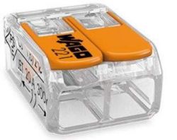
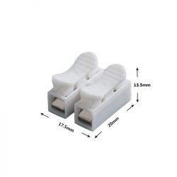
Finally, here is a well-recognized product from Wago. The quick connector presented on the right (Wago 221) is dedicated to connecting two wires with each other, but they are available in versions up to five connections. Isolated ends of wires are placed in the connector, which are snapped by pressing a lever.
Thanks to the lever, fastening and unfastening the connector is very easy - the connection is extremely reusable. Additional accessories for Wago connectors are also available, which allow, for example, to permanently mount the entire connector block in the housing.
Summary
In the case of all connection options presented above, it is worth remembering that some of them - such as cubes or nuts - are extremely universal and very popular, while others are extremely specialized for a specific application. You should always take the trouble to choose the right connector to make connections in the power grid or other installation we are building.
Source: https://www.eeweb.com/profile/aubrey-kagan/ar...ive-approaches-to-connecting-electrical-wires
This method, while it actually allows two wires to be connected, has its drawbacks. Making such connections is very tedious, especially if there should be many of them in a given installation. In addition, the length of the cable used for the connection is large, which translates into how much less wire we have to install, if there are really a lot of such connections, or how much more we have to pay for the wiring of the system (not including labor and personnel costs). that will make these connections). Importantly, such connections cannot be made under voltage under any circumstances, which is sometimes required (and what the connectors are for).
Caution
Just because you can connect two wires together doesn't mean you should connect them. They often differ in spacing and the type of conductor (i.e. wire vs line). The thinnest wire in the entire system must be capable of carrying the maximum circuit current. Moreover, the connection between the two wires can increase the series resistance further, especially if the connection is not good or is not matched to the diameter of the wire, for example. This can lead to the connection becoming too hot.
Depending on the voltage and current, there are other standards governing this type of connection. These standards exist for a reason and if you ignore them you do so at your own risk. Sometimes it ends in very unexpected or unpleasant ways. A typical example provided by the author of the article is a rejection of a fire compensation claim due to the use of an inappropriate connector in the power network, even if the connector is in a completely different place in the circuit than the fire occurred. With that in mind, let's take a look at the most popular and used cable connectors for electrical wiring.
Electric Cube
If you want to connect several different circuits with each other, you can use an electrical cube as shown on the left. The subject of cubes is very wide - this is a huge group of connectors that would be difficult to cover in this paragraph, so let's just stop presenting this very popular connector here - most of us had the opportunity to use this type of connection.
"Nuts" for wires
These types of connectors as shown on the right (Molex 0191600039) come in many colors and sizes. They are very popular in electrical installations (not as much in Poland as, for example, in the USA). They are used for connections in the power grid within the premises. The nut consists of a truncated cone made of an insulating material with a thread inside.
The use of such a connection is very simple - take the two isolated ends of the cable, insert them into the cone and just twist. Such a nut allows you to easily connect even grossly mismatched wire diameters, wire with a rope, and also allows you to connect two, three or even four wires at once. Provided that all of the exposed conductors are in the insulated cone, the connection is fully insulated. However, the joint itself is not very strong and a more forceful tug can cause it to disconnect, meaning you should consider whether there may be any mechanical stress in your application. The advantage of this connector is the fact that it can also be unscrewed to allow modifications.
Fork terminals
Anyone familiar with automotive wiring will know what fork terminals look like. For those who have not heard about them, on the left there are two photos showing such a connector: at the top - in the female version (Panduit DNF18-250-M) and at the bottom - in the male version (Panduit DNF14-250FIM-M).
Such terminals are crimped on insulated wires with the help of a special device - a crimping tool. Connectors are available in a wide range of insulation colors; very often (as in this case) the color is also an indicator of the recommended thickness of the wire on which the terminal should be crimped.
Usually the "spike" part of this connection is attached to a relay or other device block, and the other part is put on it and sits on the cable, however, as can be seen in the lower left photo, there are also these types of crimp connectors.
Make sure that the entire connection is completely insulated. This is achieved by special connectors that insulate the connection. Fork connectors of this type offer a fairly high resistance to accidental disconnection, even in the event of stronger pulls.
Butt crimp connections
These connectors use the same tools for both crimping and insulation colors as spade lugs, butt connectors (right for examplePhoenix Contact connector 3240061) are often found in the same manufacturer series as the fork terminals.
Such a connector is simply a metal tube (sometimes insulated) into which the stripped end of one wire is placed at one end of the tube, crimped, and repeated for the other wire on the other end.
Ball joints ( bullet connector )
The above-mentioned crimp connection is eternal. However, there is an intersection between a butt joint and a fork joint which is often referred to as a "ball joint" or more commonly in English. bullet connector "Shown on the left is a pair of these Panduit connectors: EBV18-4MB-Q and EBV18-4B-Q.
This type of connection consists of a bullet-shaped metal tube (with a wire clamped on one side), and a similar tube in which the so-called the 'bullet' retracts. An electric wire is also connected to the other tube.
Scotchlok quick coupler
Sometimes we want to use an existing cable for the connection. Of course, you can always cut it and make a three-way connection, for example. There is also a not very elegant and correct practice to remove a small section of insulation on the wire and wrap / solder the tap.
However, a much better solution is available - Scotchlock couplings shown on the right.
This connector has two paths. The main wire (in insulation) is inserted into one of them, and the tap is inserted into the other. The entire connector is closed on both wires, which may require the use of pliers, especially with larger wire cross-sections or thicker insulation. When closing the connector, a special blade is pressed into the insulation, and after passing through it, it touches the inner conductor, short-circuiting both wires located in the element. This type of technology (contact cutting of insulation) is called IDT.
IDT butt connectors
Now that we've introduced one IDT connector, we can see a few more of this type. The photo on the left shows an exemplary IDT butt joint (Keystone 8377). There are many series of these types of connectors, such as the Keystone i-Clamp shown and the Coolsplice series from TE Connectivity.
Wago quick coupler
Finally, here is a well-recognized product from Wago. The quick connector presented on the right (Wago 221) is dedicated to connecting two wires with each other, but they are available in versions up to five connections. Isolated ends of wires are placed in the connector, which are snapped by pressing a lever.
Thanks to the lever, fastening and unfastening the connector is very easy - the connection is extremely reusable. Additional accessories for Wago connectors are also available, which allow, for example, to permanently mount the entire connector block in the housing.
Summary
In the case of all connection options presented above, it is worth remembering that some of them - such as cubes or nuts - are extremely universal and very popular, while others are extremely specialized for a specific application. You should always take the trouble to choose the right connector to make connections in the power grid or other installation we are building.
Source: https://www.eeweb.com/profile/aubrey-kagan/ar...ive-approaches-to-connecting-electrical-wires


