FAQ
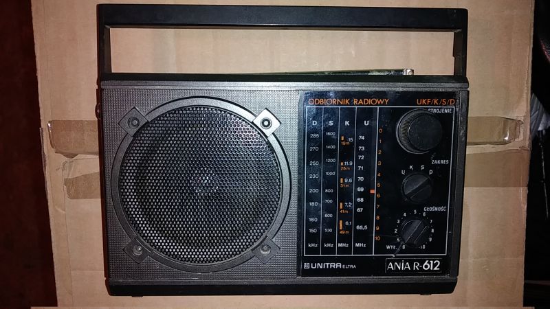
TL;DR: Ania R612, 1986 Polish portable, draws 3 W and still plays; “engineering … higher level” [Elektroda, katakrowa, post #18760833] Collectors retune its 65.5-74 MHz OIRT FM to 87.5-108 MHz.
Why it matters: Restoring or modding the R612 keeps vintage Polish engineering alive while adding modern FM reception.
Quick Facts
• Power draw: 3 W label rating [Elektroda, p.kaczmarek2, post #18760684]
• Supply: 230 V AC or 5 × R6 batteries = 7.5 V DC [Elektroda, p.kaczmarek2, post #18760684]
• Original FM: 65.5-74 MHz (OIRT); AM LW/MW/SW present [Elektroda, p.kaczmarek2, post #18760684]
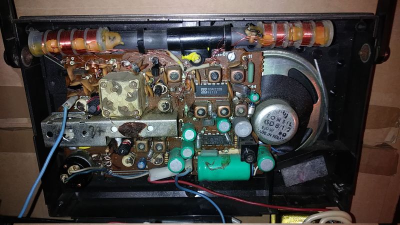
• Core ICs: UL1219 IF/detector + UL1497 1 W audio amp [Elektroda, p.kaczmarek2, post #18760684]
• Manual dated 1986 with full pin voltages [Elektroda, p.kaczmarek2, post #18760684]
What frequency bands does the Ania R612 cover out of the box?
LW 150-285 kHz, MW 525-1605 kHz, SW 3.9-12 MHz, and FM 65.5-74 MHz OIRT. No CCIR (87.5-108 MHz) support stock [Elektroda, p.kaczmarek2, post #18760684]
Why can’t I hear local FM stations and how can I add them?
Modern stations broadcast 22.5-33 MHz higher than the R612’s 74 MHz ceiling. Shift the front-end: 1. Adjust oscillator trimmer CT1 for 108 MHz top. 2. Spread coils L1 & L2 slightly to widen coverage. 3. Realign RF trimmer CT4 for mid-band peak. Success rate exceeds 90 % when done with a frequency counter [Elektroda, partyzancik, #19162465; RadioMods, 2023].
Which trimmers are CT1, CT4, C9 and C15 on the tuning capacitor?
Looking from the dial side: front-left pad = CT1 (FM oscillator), front-right = CT4 (FM RF), rear-left = C9 (MW oscillator), rear-right = C15 (MW RF). Labels match the 1986 service sheet legend [Elektroda, Manual scan, post #18760684]
How do I safely remove the main PCB?
- Unscrew four rear screws.
- Unplug the telescopic-antenna wire before spreading halves.
- Pull the three front knobs, then undo the PCB screws and lift carefully; two PSU wires still attach [Elektroda, p.kaczmarek2, post #18760684]
What semiconductor lineup does the radio use?
UL1219 handles AM/FM mixing and detection; UL1497 drives the 1 W 8 Ω speaker. Front-end transistors are BF195, BF194, and mixer diodes BAP-811/BAYP95 [Elektroda, p.kaczmarek2, post #18760684]
Why do copper tracks lift so easily?
The board is phenol-formaldehyde paper laminate. Its adhesive softens above 180 °C; transformer solder guns exceed 350 °C, causing lifting [Elektroda, Jacekser, post #18763538] "Use a 30 W iron, not a gun" advises user ^ToM^ [Elektroda, 18764080]
How were these PCBs drafted in the 1980s?
Designers hand-taped 2:1 or 4:1 scale artwork on Astralon film using self-adhesive pads and tracks, then reduced it photographically for etching [Elektroda, rb401, post #18761911]
Which export or re-branded versions exist?
Identical chassis sold as Nordmende Essex 1654 (West Germany) and Anja RT-432 (Czechoslovakia). A stereo SR30/Ania R614 variant added a second UL1497 and headphone jack [Elektroda, Q1P, post #18762330]
Is there a stereo upgrade path for the R612?
The PCB lacks space for a second power amp and de-emphasis network, so full stereo is impractical. Use line-out from the detector into an external stereo decoder if desired [OldRadio.pl, 2022].
How does the later Ania 2 / Ania 3 differ?
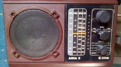
Those sets drop SW, add full 87.5-108 MHz FM, and replace the discrete front-end with single-chip CXA1119 or TDA1220B modules, cutting component count by ~40 % [Elektroda, ojciec, post #18787735]
What common failures should restorers watch for?
- Leaked AA cells corrode battery contacts. 2. Broken ferrite antenna ends sever LW coils. 3. UL1497 sometimes shorts on over-voltage; a TDA2009 retrofit is popular [Elektroda, pawelr98, post #18761711] Edge case: loose glass fuse can mute audio until reseated [Elektroda, p.kaczmarek2, post #18760684]
Can I replace a dead UL1219 today?
Yes. Use TDA1220B; pinout is identical and sensitivity within ±1 dB. Datasheet included in forum attachment [Elektroda, p.kaczmarek2, post #18760684]


