Hello colleagues.
Using the TV in a dark room sometimes causes eye fatigue due to the brightness of the screen. This is no discovery - you can turn on the lamp and you're done.
You can also turn on the LED strip on the back of the TV and turn it off when you are finished watching. However, it is always an additional activity.
The project below concerns the automation of the above process.
The basic assumptions are:
1. Automatic switching on of the backlight when dusk falls.
2. Gentle and smooth brightening of the LEDs so that the viewers do not notice the moment of switching on.
3. A gentle fading after switching on the light in the room.
4. Maintaining the light for about 30 seconds. after turning off the TV - time to put the remote control down and get to bed (this is my case).
5. Non-invasive assembly that does not require interference with the TV circuits (warranty maintenance requirement).
I do not boast of photos here, because what is there to photograph. The device was built quite a long time ago and I did not think about DIY then.
I was once gifted with a damaged 24V / 2A power supply, which I managed to fix quite simply. Shapely and transparent design, importantly, the manufacturer regretted the silicone gel, making it easier for me to make changes.
Finally, the power supply and the driver fit into the housing, where I placed the necessary connectors on one side of it:
- mains power socket
- LED connection socket
- photoresistor socket
- potentiometer
From the opposite wall comes a cable terminated with a power plug, which powers the TV.
For lighting, I used the remains of LED strips that remained after some robots, just - they were different. The 24V part, the 12V part, cold and warm. Just right for such a purpose. In addition, an aluminum section in the form of an angle bar and a light strip is ready.
I attached the strip to the sheet metal TV casing using the existing screws that fix the sheet metal rear wall.
The photoresistor is placed under the screen so that it is not affected by its light.
This is actually so much about the description of the mechanical structure.
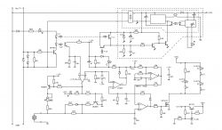
As for the electrical system, its expansion was a consequence of the implementation of the above-mentioned assumptions. It is, after all, nothing more than an extension of the well-known twilight switch.
In the end, the LED strips turned out to be too bright, so after finishing the works, I added resistors to balance the brightness of the background and the TV screen.

The LEDs visible in the diagram are small "fleas" mounted only to illustrate the logical states in the system. It allowed me to start the system faster and observe the operation on the table.
Using the TV in a dark room sometimes causes eye fatigue due to the brightness of the screen. This is no discovery - you can turn on the lamp and you're done.
You can also turn on the LED strip on the back of the TV and turn it off when you are finished watching. However, it is always an additional activity.
The project below concerns the automation of the above process.
The basic assumptions are:
1. Automatic switching on of the backlight when dusk falls.
2. Gentle and smooth brightening of the LEDs so that the viewers do not notice the moment of switching on.
3. A gentle fading after switching on the light in the room.
4. Maintaining the light for about 30 seconds. after turning off the TV - time to put the remote control down and get to bed (this is my case).
5. Non-invasive assembly that does not require interference with the TV circuits (warranty maintenance requirement).
I do not boast of photos here, because what is there to photograph. The device was built quite a long time ago and I did not think about DIY then.
I was once gifted with a damaged 24V / 2A power supply, which I managed to fix quite simply. Shapely and transparent design, importantly, the manufacturer regretted the silicone gel, making it easier for me to make changes.
Finally, the power supply and the driver fit into the housing, where I placed the necessary connectors on one side of it:
- mains power socket
- LED connection socket
- photoresistor socket
- potentiometer
From the opposite wall comes a cable terminated with a power plug, which powers the TV.
For lighting, I used the remains of LED strips that remained after some robots, just - they were different. The 24V part, the 12V part, cold and warm. Just right for such a purpose. In addition, an aluminum section in the form of an angle bar and a light strip is ready.
I attached the strip to the sheet metal TV casing using the existing screws that fix the sheet metal rear wall.
The photoresistor is placed under the screen so that it is not affected by its light.
This is actually so much about the description of the mechanical structure.
As for the electrical system, its expansion was a consequence of the implementation of the above-mentioned assumptions. It is, after all, nothing more than an extension of the well-known twilight switch.
In the end, the LED strips turned out to be too bright, so after finishing the works, I added resistors to balance the brightness of the background and the TV screen.

The LEDs visible in the diagram are small "fleas" mounted only to illustrate the logical states in the system. It allowed me to start the system faster and observe the operation on the table.
Cool? Ranking DIY


