Hello my dears.
I invite you to a short teardown of another 'smart' relay from the Tuya/SmartLife/eWeLink family. I will check here what elements it is made of, and (above all) what kind of WiFi module is inside. Depending on this, I will assess whether it is worth buying it with the thought of uploading your own input to it, or maybe it is not possible at all ...
Purchase NF101-A, kit content
I bought the NF101-A some time ago for about $6, maybe $7, which is less than PLN 30 on one of the Chinese portals with free shipping.
When buying this product, I recommend checking carefully whether it is the one I am describing here, because there are different versions and they differ inside. This is especially important if someone, when ordering it, expects to get a version with a specific WiFi module inside ... although it is often a lottery - the module may change with the product version to another, even though the housing is the same from the outside as before.
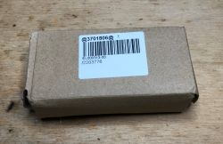
Below is the set I received:
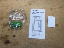
Instructions (in which the word Sonoff appears - did they forget to change the names when making the clone?):
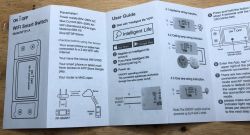
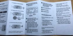
On the other hand, it's the same only in Chinese, so you can skip it.
And most importantly:
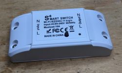
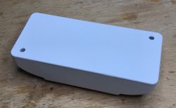
The inside of the NF101-A
I have discussed the operation of smart devices and their phone applications on the forum several times, so let's look inside right away.
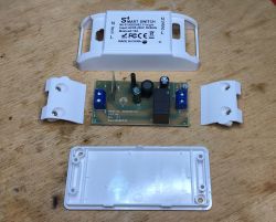
Screw terminal protection removed:
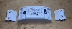
Then just pry the plastic:

It's time to look at the plate. You can see that it is a single-sided board, it looks quite economical, but nothing more is needed for such a simple layout.
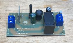
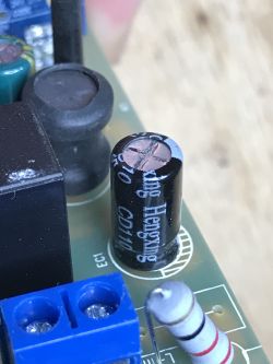
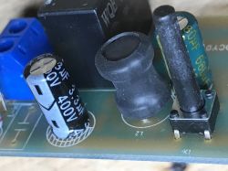
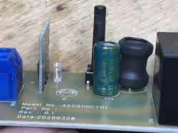
The fuse resistor is there, but there is no varistor, no surge protection, no class X capacitor, no extra noise emission protection, nothing.
Extremely poor. I've seen varistors in similar products.
The capacitor just behind the bridge is Hengxing, while the one on the low voltage side is Huahong, low ESR.
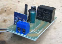
The heart of the relay is unfortunately WB2S, there is no ESP here:
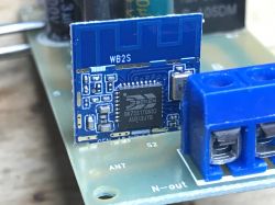
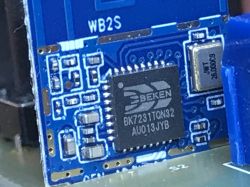
This module is WB2S, implemented on BK7231TQN32 (actually: BK7231T, QN32 means QFN 32 pin housing). On the board next to it you can see a 26MHz quartz resonator.
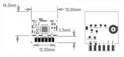
And now the bottom of the plate:
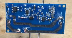
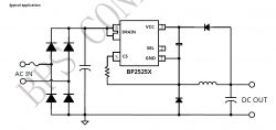
MB8S rectifier bridge, BP2525 transformerless power supply controller with necessary elements, configured as below:
Then the regulator LDO 6206A (XC6206) providing 3.3V for the WB2S module, and a single transistor controlling the relay (J3Y - S8050 as usual).
I have already drawn a diagram of a similar product. I put it below, here it is basically very similar (only a different WiFi module and a different power supply system):

The circuit from the diagram above is also slightly better protected than the one from the product I am discussing here.
Workstation for programming and debugging WB2S
There is an opinion on the Internet that WB2S cannot be programmed (there are no tools to upload a batch or there is no appropriate, complete SDK to create a batch). In my opinion, this opinion is wrong, because I have already managed to choose a toolchain and run one of the "Chinese" batch projects on BK7231, which I will describe soon.
For now, I will only present the preparation of the workstation with this layout.
Pins you will need:
- RX and TX (for programming)
- 2RX and 2TX (for checking the UART output log from the system)
- of course ground and power supply, in this case I decided to connect with 5V before LDO 3.3V
NOTE: if we want to power from USB, we need to remove the large electrolytic capacitor located in front of the LDO. It is often in the order of 680uF, and such a large capacitance connected to USB will draw too much current at start-up, which results in resetting the USB device and problems with programming the WB2S!
I remind you of the WB2S outputs:
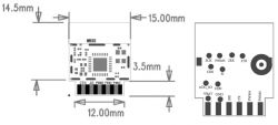
Soldered cables to RX and TX (pads at the base of the module at the PCB) and a red cable to 5V (before LDO):
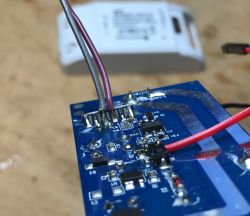
Soldered 2RX and 2TX (tiny test pads on the "back" of the module):
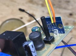
In order to secure the connections, I allowed myself to temporarily use hot glue:
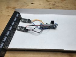
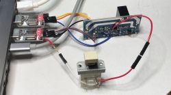
The final working environment. You can see the necessary switch (programming needs) and two UART to USB adapters, one for programming, the other for reading the printf output:
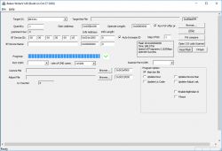
For batch programming I use BKwriter (bk_writer1.60), the programming/reading procedure is simple. We run the action in the program, then turn off the WB2S from the power supply (and only from the power supply) with the button, and after a while we restore the power supply. The program should continue running as in the screenshot:
I am using RealTerm to read information from the UART as in the screenshot below:
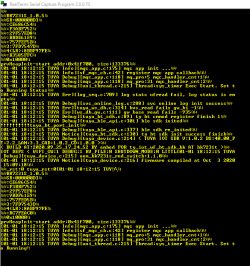
Your working environment is ready! WB2S can be programmed.
For further adventures with WB2S, I invite you here:
WB2S/BK7231 Tutorial - we create our own firmware - UDP/TCP/HTTP/MQTT .
Related Topics
Below is an incomplete list of my topics about smart home devices. In these topics, I put a lot of emphasis on showing the inside of the device and the elements used inside, and above all the WiFi module, because information about what WiFi module sits inside is very useful for many users - some people buy such products with the intention, for example, of uploading their own firmware or something like Tasmot, and it is not possible when, for example, there is no ESP8266 inside.
- BW-LT30, a WiFi adapter for a light bulb - test, teardown and ESP firmware upload (here with Hello World example for ESP on Arduino IDE)
- Electrical socket controlled by WiFi - BW-SHP8 - start-up and tests (based on the TYWE2S module)
- Test and interior of the BW-SS3, a WiFi light switch from Blitzwolf (based on the TYWE3S module)
- Socket/plug with WiFi PS-16-M and eWeLink/Coolkit application - test and teardown (in the middle sits loose ESP8285)
- SmartLife switch - test, interior and programming of the WiFi light switch (similar switch, but without RF and description of programming it in Arduino via wires)
- SC3-01 SmartLife switch and ESP firmware upload via WIFI (tuya-convert/OTA) (this time programming via WiFi, no need to open the case, no soldering wires)
- QTouch WiFi switch plugged into the L cable only - test, interior, diagram (an interesting switch, which is implemented on a thyristor and not on a relay, but also has ESP8285 inside)
- WiFi SmartLife single-color LED strip dimmer - test, interior, diagram (interesting LED strip driver on MOSFET and WB3S transistor)
- SmartSwitch Tuya WL-SW01_16 16A WiFi - test, inside (WB2S) (slightly larger relay for higher current)
- Sonoff Basic ZBR3, the famous relay in the Zigbee version. Interior, diagram (small variety from WiFi)
- WiFi door/window opening sensor - test, interior, integration with the rest of the devices (sensor based on the XR809/XR2 module)
- Zigbee Thermometer/Hygrometer with LCD TS0201 RSH-Z-Bee-HS01 Tuya (battery powered temperature/humidity display, this time on Zigbee)
- The inside of the TH06 clock/thermometer/hygrometer and reverse engineering its protocol (calendar on WB3S and a bit about processing packets with data in binary format through a C program)
- Four-channel WiFi transmitter Tuya SmartLife 4CH 10A [diagram] (slightly larger driver, unfortunately on WB3S)
- Own open firmware for XR809 compatible with Tasmota HTTP/Home Assistant (detailed description of how to create your own batch for door sensor on XR809)
- Recessed switch/relay RR400ZB/TS011F Zigbee - test, diagram - another Zigbee driver
- WiFi camera Tuya RPP06 1080P - application possibilities, test, interior - this time the camera for a change
Additionally, a topic about Tasmot and the DIY version of the WiFi relay:
- ESP8266 and Tasmota - controlling the WiFi relay step by step
Additionally, topics about the Aqara series (not on WiFi, but on Zigbee):
- Aqara WSDCGQ11LM door opening sensor for Zigbee - test, interior, diagrams
- Temperature/pressure/humidity sensor Aqara WSDCGQ11LM - interior, diagrams
- Aqara RTCGQ11LM motion sensor - interior, refresh time modification
Summary
Unfortunately, the NF101A looks poorer than its counterparts, and its board has empty spaces for elements that the manufacturer omitted to further cut costs. In addition, there is a WB2S module inside, for which there is no open source input available at the moment, although I am going to try to change that.
I did not test the mobile application from this relay this time, but I think it was not necessary. It was tested in other topics.
The relay module itself from the topic served as a test environment for WB2S programming, which I described here .
I attach the BP2525 data sheet:
Cool? Ranking DIY Helpful post? Buy me a coffee.


