logo elektroda
logo elektroda
X
logo elektroda

PEUGEOT BOXER III - Repair of the AdBlue tank PEUGEOT BOXER III, CITROEN JUMPER

mako122 155274 224
ADVERTISEMENT
Treść została przetłumaczona polish » english Zobacz oryginalną wersję tematu
  • #121 20771088
    mako122
    Level 12  

    bbmax wrote:
    P20E8 driver upgrade needs to be done


    Can you elaborate on the topic? Where can such an upgrade be done? Only at the ASO? What changes does this upgrade make?
  • ADVERTISEMENT
  • #122 20771879
    bbmax
    Level 15  

    Dealer, purchase your own equipment or go to a friend's workshop in Karpacz where I left my can adapter :)
    Diagram of the urea tank connector and repair instructions. Diagram of the urea tank connector and repair instructions.
  • #123 20790395
    _Hose_
    Level 11  
    _Hose_ wrote:
    I rode at a time when there was no sign of rain the week before or the week after, heat and nothing else. It's possible that something wasn't making contact somewhere (even though I've never done anything there) and now it's ok. The most important thing is that it works, at least it still works 😁


    It doesn't work anymore, the problem is back.
    Does the 308 T9 have this device identical to the Boxer?
    I am asking about electronics and how to diagnose it.
  • #124 20791011
    mako122
    Level 12  
    The shape of the tank is different because it must be adapted to the shape of the chassis, but the most important thing is the same. Of course, it is impossible to replace, for example, the electronic board between the Boxer and the 308 because they have different software. The capacity of the tank is different because it has a different shape, the software has different capacities, etc. You can easily try to repair the tank based on what is in this thread.
  • #125 20791342
    _Hose_
    Level 11  
    Thanks for the info. I'll take out the tank at some point and have some fun. The program is rather located in the engine controller? Is the tank plate the same as in other Peugeots? What a contraption.
  • #126 20792317
    mako122
    Level 12  
    _Hose_ wrote:
    Thanks for the info. I'll take out the tank at some point and have some fun. Is the program located in the engine controller? Is the tank plate the same as in other Peugeots? What a contraption.


    The program sits on an electronic board in the tank. The board has its own processor marked as U300 and this processor controls all the tank systems. The processor only sends information to the engine controller whether everything is OK, or sends errors. The description of the board and its circuits is located in this thread. There is also a block diagram of the board, please see post no. 5. The boards are the same in all tanks, but depending on the car, the U300 processor runs its program with different parameters, so the board cannot be swapped between different types of car. Cars have different engines, different power, etc. They each need a different dose of urea, etc. To sum up, the boards are physically the same, but have different software depending on the type of car. The board is described quite thoroughly in this thread, there are also photos of individual circuits with a description of what each circuit does. Please read this entire thread carefully before starting the repair, it will help you be better prepared for the repair. If you encounter any problem during repair, please write here on the forum, there will always be someone who will help. It is worth making a thorough visual inspection and looking for any moisture or a white coating of crystallized urea on the tile. Problems are often caused by leaks in the hydraulic system and leakage of even a small amount of urea into the part of the tank that contains the electronics.
  • #127 20829872
    marekarmata1975
    Level 4  

    Does anyone of you know what controls the AdBlue injector in Citroen C5, where to look for the other end of the circuit? I have error P2047 open circuit. The injector was functional for a short time, the injector cube was measured with an ohmmeter, it was about 20 ohms.
  • #128 20830554
    mako122
    Level 12  
    The injector is controlled directly from the engine's central computer. I don't have a diagram of your car, but I'm 99% sure it's the same in your case. Around 7 p.m. I will send you a diagram of my car, maybe it will help you locate the damage.

    Added after 8 [minutes]:

    Please look for the other end of the cable directly on one of the pins from the engine ECU (main engine controller)
  • ADVERTISEMENT
  • #129 20830596
    marekarmata1975
    Level 4  
    Thank you very much for help!
  • #130 20831186
    mako122
    Level 12  

    Electrical schematic of ECU with PIN 85 and PIN 86 and the urea injector.


    1320 - ECU (engine main computer) PIN 85 and PIN 86

    12B4 - urea injector

    ECU - Electronic Control Unit ✓ Electronic control module; The task of the control unit is to supervise the proper operation of the car engine


    I don't know if this is the case in your car, but 99% of the time the urea injector is controlled directly from the ECU.
    There may be control on other pins, but you can start by checking pins 85 and 86. Please pay attention to the colors of the wires, they should be the same at both ends, because there is no connection cube on the way (it is not in the diagram, so it should this pair of wires at both ends have the same color).
  • #131 20831200
    marekarmata1975
    Level 4  
    Super helpful, thank you.
  • #132 20864375
    tbudzynski81
    Level 1  

    Can I remove the AdBlue countdown in Peugeot Boxer 2.2 BlueHDi 165 km 2021 - it went down to 0 with the Lexia scanner?
  • #133 20864559
    harry1250
    Level 12  

    In 508, I deleted the mini Vgate iCar2 interface + FAPlite application.
  • #134 20872641
    NORBERTII
    Level 1  

    The H-bridge is needed to empty the installation of urea, so that it does not freeze after a night, for example.
    After starting the engine, the SCR system refills the installation to keep the system running.
  • #135 20887887
    slawekbu
    Level 10  

    Hello. Thank you for such a helpful topic. My patient is a Peugeot 5008 II 1.6 HDI 120 HP. After checking all the sensors, the error was on the sensor with the yellow 200 ohm wires. I cut off the yellow wires and soldered a 10k resistor to them. After this "repair", the car stopped displaying AdBlue damage. I still have a question: can this type of "repair" have any side effects?
  • #136 20905463
    mako122
    Level 12  
    Can anyone tell what is in the picture (the black part that hangs on the wires).

    A white Citroën Berlingo parked in a snowy parking lot. View from under a car with a black component hanging on wires.
    A black component hanging on wires under a car chassis, surrounded by snow. A black component hanging on wires under a car chassis, surrounded by snow. Black part hanging on wires beneath a car. A vehicle's undercarriage with a component hanging on wires.


    It appears, That it is NGK NOX SENSOR SONDA ?
  • #139 20906617
    mako122
    Level 12  
    Yes this is the NOX probe

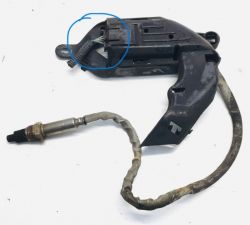
    Damaged NOX sensor with casing and wire.


    It was not secured with a bolt and the entire cover with the NOX probe popped out of the latches and hung under the car. There was an error on the dashboard " no communication with the NOX probe" The reason for this was flooding the connector with salt water and dirt from the road (slush).
  • ADVERTISEMENT
  • #140 20909782
    Reflekt
    Level 17  
    >>20445663

    welcome , I have a similar fault resistance on smd thermistor on heating board 380ohm at 12stC. I wanted to put it new in the hole with the wires that are marked in the picture will this solution pass the test ?
  • #141 20910160
    harry1250
    Level 12  
    Add in series resistors in the yellow wires
  • #142 20910186
    Reflekt
    Level 17  
    that is, at this temperature it should have a thermistor of 17.23kohm , I will solder 17kohm and check how the resistance changes at different temperatures of water in the tank
  • #143 20913040
    Reflekt
    Level 17  
    I soldered 15kohm , after three attempts ( warming up the engine to operating temp) no errors .
  • #144 20913130
    mako122
    Level 12  
    Well, and great!!! Keep it up!!!
    And 5k left in your pocket.
  • #145 20914410
    melaswlkp
    Level 10  

    You have to drive the car only after about 15 km, the Adblue system is checked.
    .
  • ADVERTISEMENT
  • #146 20915477
    Reflekt
    Level 17  
    all the routes I have covered were much more than 20km in total there were already 6 of them and no errors .
  • #147 20971222
    lukaszjgjg
    Level 9  

    >>20419654
    You can always use an alternative shutdown service. But just like you, I support the contribution and a lot of work put in by the creator of the topic.
  • #148 20973283
    Andrezej1976
    Level 1  

    Hello everyone, I have a 2018 Peugeot 3008 - 2 l diesel - like most users, I have a problem with the AdBlue tank. I dismantled the tank, disassembled all the electronics and measured the parameters. In the non-removable part, I inserted a 10kohm resistor on the yellow wires from the heating plate. After measuring the parameters, the rest seems to be good, the only difference in my case is in the non-removable part, it is on the black plug from the fuel level, because this plug has four cables and not three, but after the measurements it seems to be good. After assembling the tank to the car and starting it, I noticed a communication error and, of course, a problem with the pressure. The only strange thing is that the computer shows zero bars, not four as before. My problem is that after unplugging the plug from the J3 board on the heating elements such as Pump - valve - battery, the heating sensors show me different parameters than those shown by the colleague from the post above, namely my indications are as follows:
    A- heating plate Urea - 1.3 ohm
    B- Short urea cable - 27 ohm
    C- Green circuit - 51 ohms
    D- yellow circuit - 49 ohms
    E- circuit Blue - 12 ohms
    F- white circuit - 13 ohms
    G- Cable from the tank to the injection 0.0 ohm

    And the indications - Mako 122
    - Before a detailed description, I put the correct resistance values of all circuits here:
    A) plate heating the urea in the tank (there is no direct access to it) - 1.3 Ω
    B) cable connecting the urea filter with the pump assembly (approximately 30 cm long) - 27.0 Ω
    C) "green" circuit, pump heating - 55.0 Ω
    D) "yellow" circuit, solenoid valve heating - 55.0 Ω
    E) "blue" circuit, urea battery heating - 212.0 Ω
    F) "white" circuit, heating the elbow at the point where the urea exits the tank - 22.0 Ω
    G) heating circuit of the tube between the tank and the injector (about 1.5 m) - 2.5 Ω

    And now I don`t know if these parameters can differ, because I had four cables on the fuel level plug, and in most of you there are three, and after disassembling the entire pump plate and all the elements, it seems to me that it is the same plate, only with the difference in the fuel plug, is it possible that two or all of the heating sensors are broken at once? I checked the pump according to the instructions in the video and everything seems to be fine, it draws water and the pressure also seems to be good.
    Please help. Thank you.
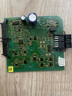
    Close-up of a circuit board from a Peugeot 3008 electronic module.
  • #149 20973890
    sylwekpi
    Level 10  

    Has anyone had a problem with sealing the connection between the tank and the pipe leading to the injector? In my case, 90% of the fluid escapes from here, which is why I think the pressure in the system is too low. The tank is dirty and there are crystals under the car. How to seal it? Add some O-ring? Is it possible to replace the cable? And this one is not cheap, probably around PLN 700.... Close-up of the connection between a tank and a tube leading to an injector, showing fluid residue.
  • #150 20975951
    Reflekt
    Level 17  
    Andrezej1976
    the heater has a short circuit in the 1.5 m cable, you need to find where the wires are short-circuiting or install a resistor with a heat sink in the plug to cheat the controller and check if the system will start.

Topic summary

The discussion focuses on the repair and diagnostics of the AdBlue tank system in PEUGEOT BOXER III and CITROEN JUMPER vehicles, addressing common errors such as P20E8 (low urea pressure) and communication faults with the SCR (Selective Catalytic Reduction) system. Key issues include sensor failures (urea level sensor, temperature sensors on the heating plate and heater circuits), pump and solenoid valve malfunctions, and electronic board damage due to urea corrosion. The tank electronics include a microcontroller (R5F21368WKFP), pump driver circuits with an H-bridge allowing bidirectional pump control, and multiple heating circuits to prevent AdBlue freezing. Repair strategies involve visual inspection for leaks and corrosion, testing and bypassing faulty sensors (e.g., using resistor voltage dividers to simulate full tank level), replacing damaged temperature sensors with 10 kΩ thermistors, and verifying heating circuit resistances. The system requires clearing ECU errors via diagnostic tools (DiagBox) after repairs, as error messages do not always clear automatically. Some users report that the system self-bleeds air over driving distance, negating the need for manual bleeding. The pressure sensor model HM8500J is identified as critical for monitoring AdBlue pressure, with detailed testing performed. The discussion also covers the challenges of tank disassembly and repair, recommending plastic welding over gluing due to ABS plastic construction. Some users mention software or ECU programming to disable or neutralize the AdBlue system as a last resort. The importance of proper electrical connections and CAN bus communication is emphasized, as loss of communication leads to power cutoff to the tank electronics after about 30 seconds. Overall, the thread provides detailed technical insights, component specifications, diagnostic procedures, and practical repair tips for maintaining and restoring AdBlue tank functionality in PSA group diesel vehicles.
Summary generated by the language model.
ADVERTISEMENT