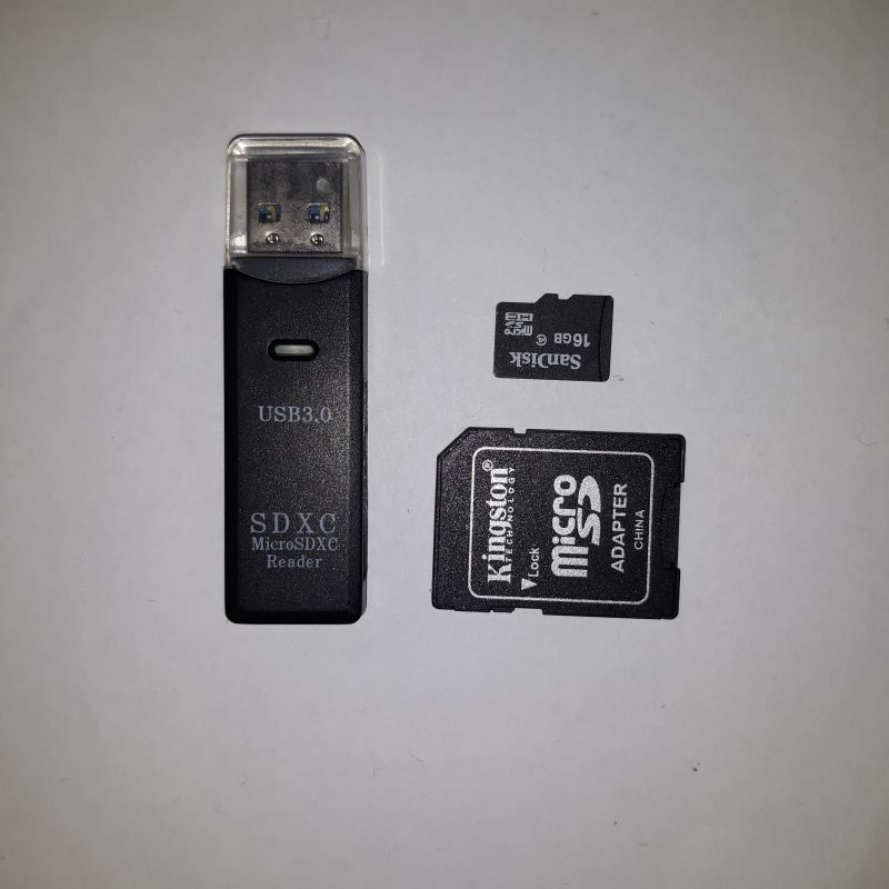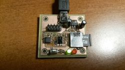
In this article, I will describe the reason for inventing and designing a tester for microSD memory cards, which will be used to check some interesting properties of cards.
Cause of the uprising
MMC / SD / microSD cards, apart from their natural applications, are also liked by fans of microcontrollers for several reasons:
* can be used as an additional memory with a really large capacity (both for reading, e.g. when displaying photos when the microcontroller controls the digital image frame, and for saving e.g. measurement results from a thermometer
* simplify the exchange of this data with a PC or telephone
* communicate with the outside world either using the SD or SPI protocol (the latter is extremely easy to implement)
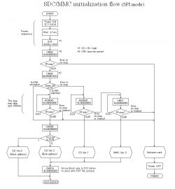
At the beginning, there were MMC cards (up to 128MB, I think), later they were replaced by SD cards (identical in size), and then mini and micro SD cards were created. There were "regular", "SDHC" and "SDXC" cards. Detecting the type of card (and thus the way of addressing it) can be difficult. This is perfectly described in the article below:
http://elm-chan.org/docs/mmc/mmc_e.html
and this is perfectly illustrated by the diagram below:
The SPI protocol is a serial full-duplex data transmission protocol in which:
* on the MISO (Master Input Slave Output) line, the data goes from the card to the host (e.g. PC),
* on the MOSI line (mater Output Slave Input, the data goes from the host to the card.
* and all this happens in time with the SCLK clock signal generated by the host.
* there is also a fourth line (nCS) which ... that's it
Theoretically, it is to enable the connection of several cards to one host using the same MISO / MOSI / SCLK lines. Each card would have its own separate nCS signal that would be active while transmitting with it:
                                       VCC VCC
                                        |   |
SCLK ---+----------+----------+         R   R
MISO ---|+---------|+---------|+--------+   |
SCLK ---||+--------||+--------||+-----------+
        |||        |||        |||
	  +-------+  +-------+  +-------+
	  |Karta 1|  |Karta 2|  |Karta 3|
      +-------+  +-------+  +-------+
         |           |          |
nCS1-----+           |          |
nCS2-----------------+          |
nCS3----------------------------+
In practice, however, hardly anyone uses it and most often we deal with a single card. So what about the nCS line? Theoretically, it should be low (active) only during the transmission of 8 bits, then go high (which would signal the transmission of the entire byte)
SCLK __--__--__--__--__--__--__--__--________--__--__--__--__--__--__--__--______
MISO ------------
nCS  --______________________________--------______________________________------
In practice, however, this line may be in a low state all the time and the card does not make any difference (and our microcontroller then has one more pin for other needs). Are you sure?
Well, according to the above-mentioned diagram, just after applying power to the card, one should wait a moment and send it at least 74 clock cycles to "start up". During these warm-up cycles the nCS line should be inactive, and then after "warming up" to shutdown it may be low. And by doing so, I was able to communicate with each card without any problem.
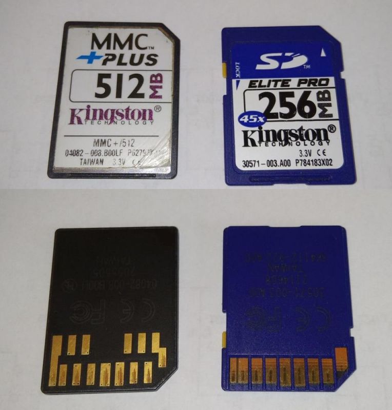
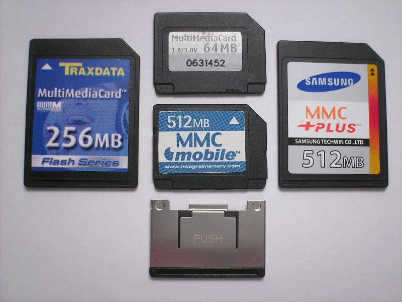
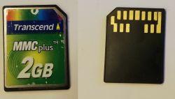
However, in a device that I once designed, the nCS line was permanently grounded (saving pins and resources). It worked on the card I had at the time. Then I bought a dozen other cards and it turned out that some "do not want to communicate". It was bad news, because I already had more boards to build the device on my desk - reworking would become cumbersome (so it was not an option). I tried to find some rule - e.g. Sandisk cards always worked, and other producers or even no-name sometimes had whims). I wanted some kind of 100% effective method of determining that would allow me to find out before buying the card, preferably by its appearance alone. Well, cards like these cards, after the manufacturer's logo are the same after all. However, not really - I discovered an interesting property:
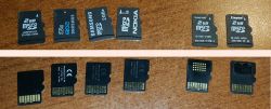
The cards on the left (operating with the nCS line always on the ground) are "smooth" on the back (either all black or with some inscriptions), and the ones on the right (capricious) have either a sticker or some strange contact areas. Always when buying cards, I asked the seller to choose "smooth". However, because I was not sure if it was a 100% effective method, I decided to create a simple device-tester with: a card slot, a button and two LEDs that, after pressing the button, perform a check and light up depending on whether the card is OK or capricious . I wanted to send the device to the seller before buying it.
Design
In order to cut costs, the device will be based on a miniature Attiny13 microcontroller. He only has 8 legs. By subtracting VCC, GND and / RESET - there are 5 pins left for your own use:
- the program is so simple that it does not require any interaction from the user (so the test button can be connected to the / RESET pin)
- two LEDs, cleverly connected to select one of the three states (0/1 / Z) which of the LEDs (respectively: red / green / none) should light up,
- MMC / SD cards require 3.3V power supply, so a stabilizer will be useful,
- and a circuit 74LVC245 for converting the voltage levels on the lines going to the card (MOSI / SCK / nCS); MISO (outgoing from the card does not require conversion)
- the microcontrollers I have (ATTINY13V) can be powered from as low as 3.3V, so the 74LVC245 converter would be redundant, but ... the USBASP programmer I use is powered from 5V and this is also the level of signals on the lines used during programming, so it could damage the attiny 'ego.
- card slot and mini USB socket for power supply
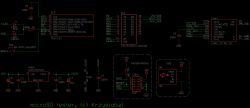
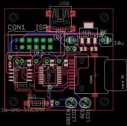
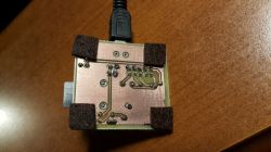
The tile, as usual, was quite nice:

ADVERTISEMENT
Software
In attiny, we only have 1024 bytes per code, so don't go crazy. The program performs 2 identical tests one after the other:
* TEST1 - attempt to communicate with the nCS card constantly on the ground
* TEST2 - setting the nCS to a high state, launching 80 warm-up cycles, returning the nCS to ground and trying to communicate
Each of the tests:
* or it will fail,
* or we manage to communicate with the card - then it determines which card we are dealing with.
Wyświetlanie wyniku testu:
dioda   | dioda    | wynik
zielona | czerwona |
--------+----------+-------
   -    |   miga   |  TEST1 fail, TEST2 fail (błąd komunikacji)
miga (*)| miga (*) |  TEST1 fail, TEST2 pass (karta kapryśna)
miga (*)|     -    |  TEST1 pass, TEST2 pass (karta ugodowa)

(*) - ilość mignięć oznacza:
1 -> karta SD VER.2 (block address)
2 -> karta SD VER.2 (byte address)
3 -> karta SD VER.1
4 -> MMC VER.3
From the cards I have:
* 4GB and 2GB cards are SD VER.2 (byte address)
* a card with a capacity of 32GB is SD VER.2 (block address) - no wonder, because on 4 bytes (32 bits) you can address a maximum of 4GB
The presentation
Kod
[syntax=C]
#include // Most basic include files
#include // Add the necessary ones
#include
#include
#include "e:\Pulpit\projekty\elektronika\Atmega - mikrokontrolery\!programy\prog-c\misc2.h"
#define CMD0 (0x40 | 0)
#define CMD1 (0x40 | 1)
#define CMD8 (0x40 | 8)
#define CMD16 (0x40 | 16)
#define CMD17 (0x40 | 17)
#define CMD24 (0x40 | 24)
#define CMD58 (0x40 | 58)
#define CMD41 (0x40 | 41)
#define CMD55 (0x40 | 55)
#define SPI_MOSI B0
#define SPI_MISO B1
#define SPI_SCLK B2
#define SPI_nCS B3
#define LED B4
void led_green() {
as_output(LED);
out(LED, 1);
}
void led_red() {
as_output(LED);
out(LED, 0);
}
void led_off() {
as_input(LED, PULLUP_OFF);
}
#define DELAY1 200
#define DELAY2 800
// makes blinks of red/green/both diodes (waits DELAY1 after each blink) and then wits DELAY2
void led_blink(bool is_red_on, bool is_green_on, uint8_t count) {
for (uint8_t i = 0; i < count; ++i) {
for (uint8_t j = 0; j < 100; ++j) {
//red and green cannot be turned on at once but turning one
//and then the other very fast makes illusion that both are turned at the same time
if (is_red_on && ((j & 1) == 0)) {
led_red();
}
if (is_green_on && ((j & 1) == 1)) {
led_green();
}
_delay_ms(DELAY1 / 100);
}
led_off();
_delay_ms(DELAY1);
}
_delay_ms(DELAY2);
}
//sends 8 bits (data) on MOSI
//receives (and returns) 8 bits on MISO
uint8_t mmc_transfer_byte(uint8_t data, bool enabled) {
uint8_t result = 0;
for (int i = 7; i >= 0; --i) {
out(SPI_MOSI, (data >> i) & 1);
out(SPI_SCLK, 1);
result |= (in(SPI_MISO)
Cool? Ranking DIY


